
Ultrasonic testing of fitting assembly for fluid conduits with a hand-held apparatus

a technology of fluid conduit and fitting assembly, which is applied in the direction of distance measurement, heat measurement, digital computer details, etc., can solve the problems of inability to cost-effectively and non-destructively evaluate the fitting assembly, the process is expensive, and the assembler is not practical if not most, and the steps are time-consuming and costly

Inactive Publication Date: 2007-10-23
SWAGELOK CO
View PDF39 Cites 54 Cited by
  • Summary
  • Abstract
  • Description
  • Claims
  • Application Information

AI Technical Summary

Benefits of technology

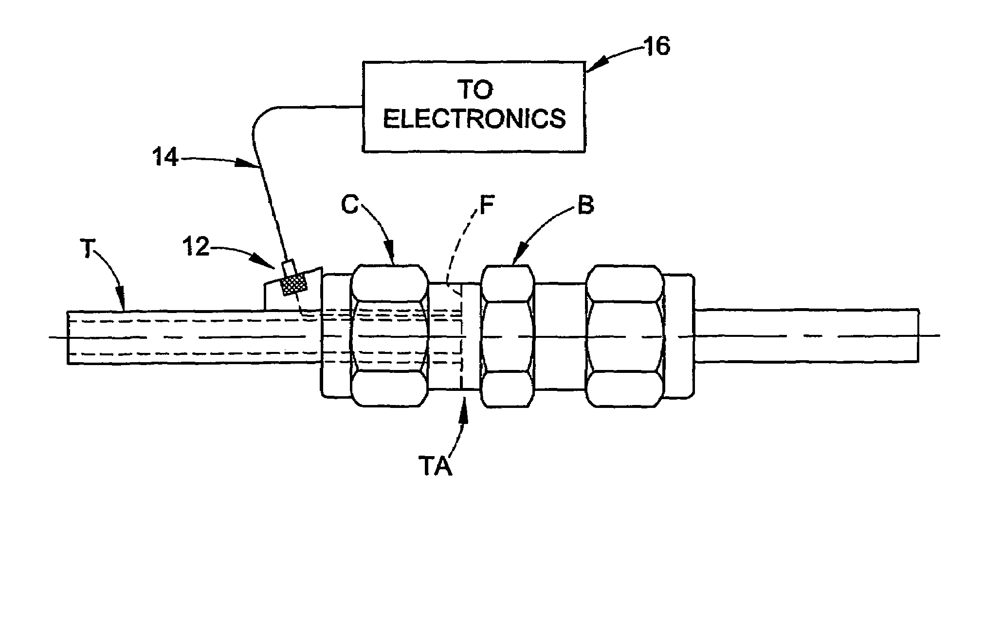
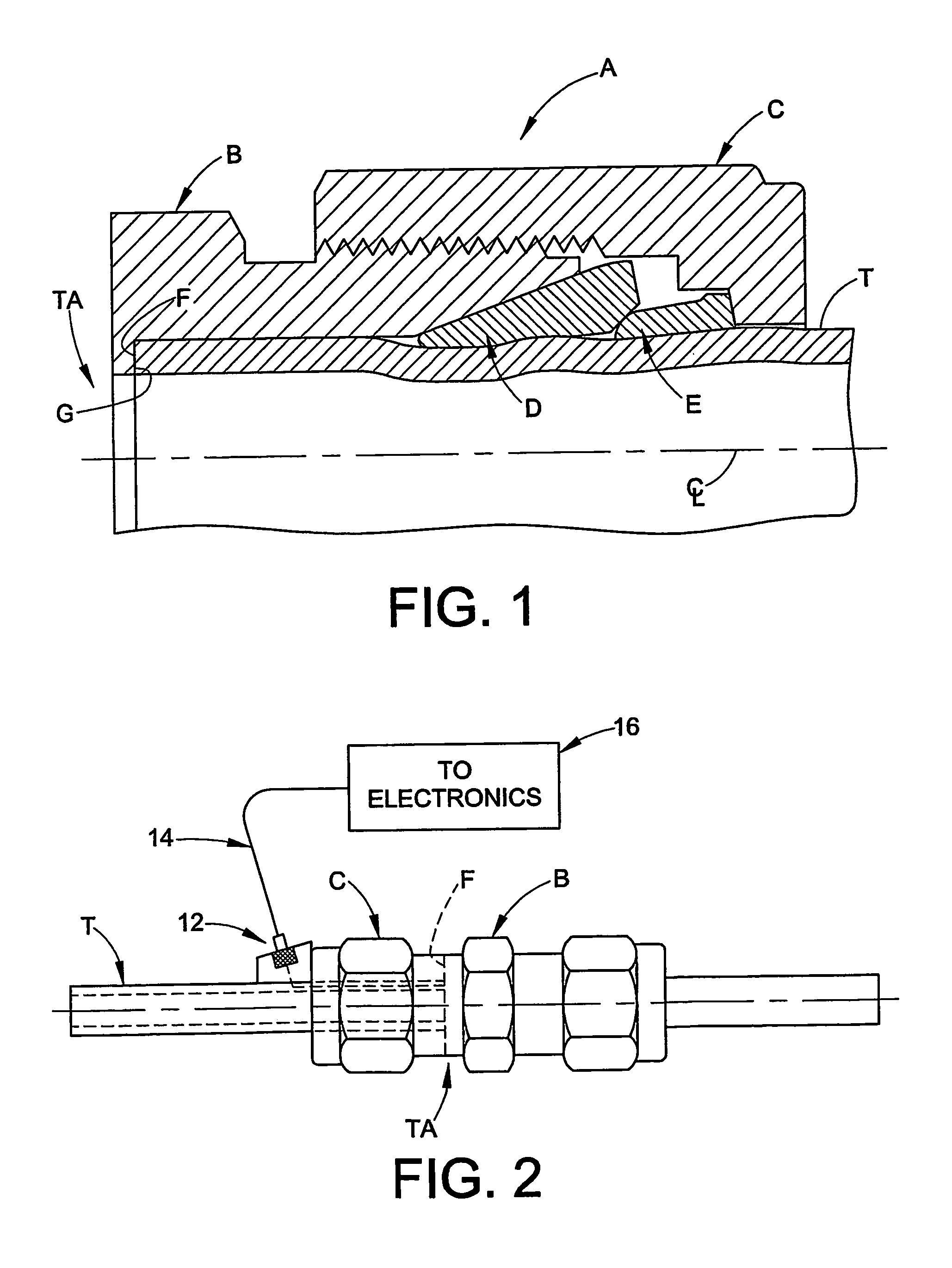
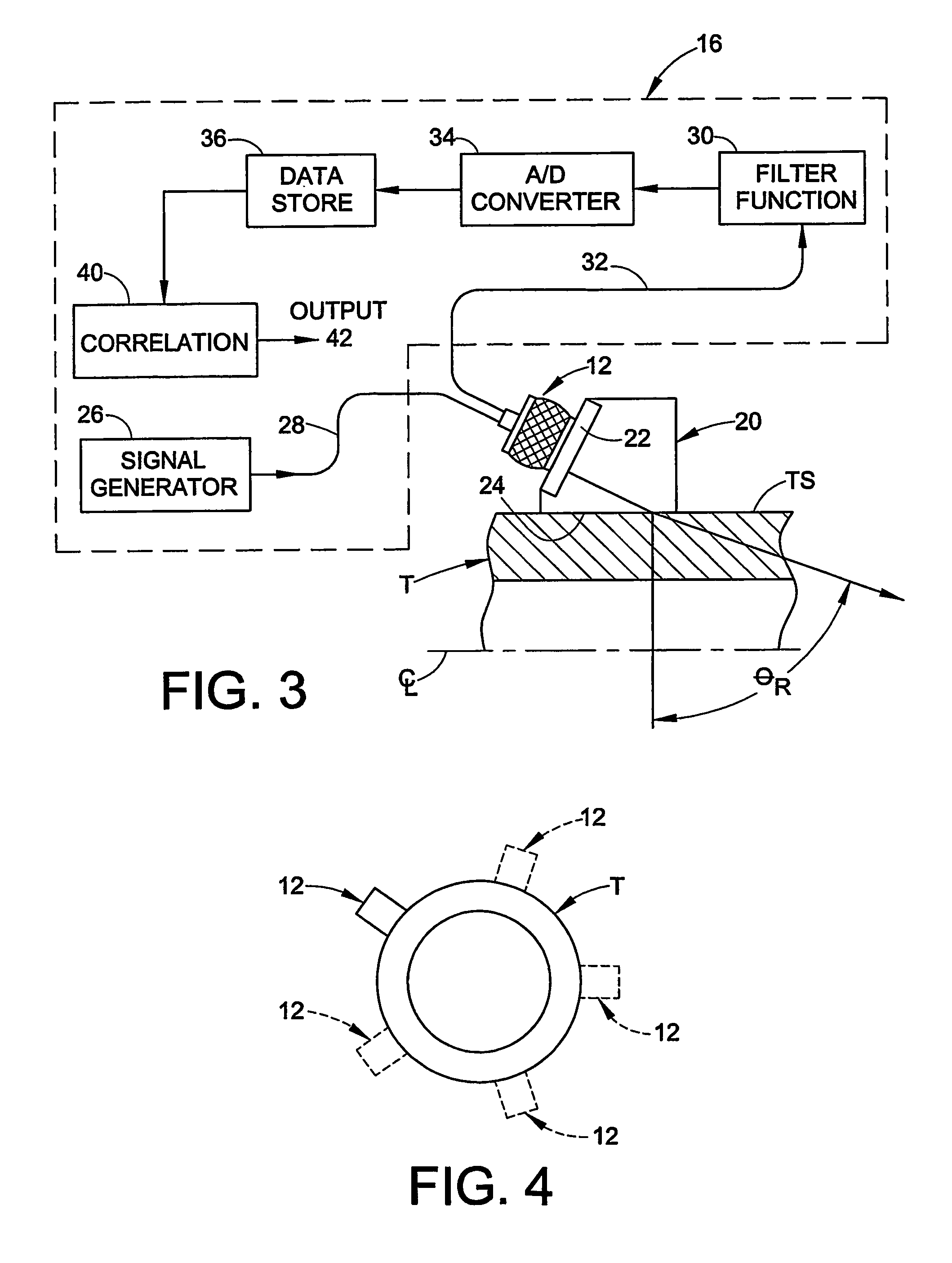
The invention is about using ultrasonic energy to determine the position of the end of a conduit, such as in a fluid coupling. The reflected energy signals are analyzed to determine the position, and correlation techniques are used to determine the quality of contact between the conduit and the surface of the fluid coupling. The invention also includes a tool that integrates a source of mechanical energy waves, an analyzer to determine the characteristics of the fitting assembly, and a gap gauge. The technical effects of the invention include improved accuracy in positioning the conduit end and detecting proper assembly of ferrules in a tube fitting.

Problems solved by technology

Inherent in the assembly process, however, is the practical circumstance that once the fitting is installed there is no cost-effective non-destructive way, known to date, to determine that the conduit is fully bottomed.
For example, it is known to use x-rays to observe the fitting condition, however, this is a very expensive process and simply not practical for many if not most assemblers.
For example, the fitting may be disassembled after pull-up, visually inspected and then reassembled, but such steps are time consuming and costly.
In another known technique, the tubing may be pre-marked in an appropriate manner prior to assembly, but this technique is subject to error in the marking or interpretation process.
None of these techniques can absolutely determine in a final assembled fitting that the conduit is bottomed, and also determine the nature or quality of the contact or abutment between the conduit and the associated structure.

Method used


Image

  • Ultrasonic testing of fitting assembly for fluid conduits with a hand-held apparatus
  • Ultrasonic testing of fitting assembly for fluid conduits with a hand-held apparatus
  • Ultrasonic testing of fitting assembly for fluid conduits with a hand-held apparatus

Examples


Embodiment Construction

[0020]1. Introduction

[0021]The present invention is directed to apparatus and methods relating to determining position of a conduit within a fluid coupling installed on the conduit. This determination may include, separately or combined, determining the axial position of an end of the conduit within a fluid coupling, and determining the quality of contact between the conduit and a surface associated with the fluid coupling.

[0022]Determining the axial position of a conduit within a fluid coupling is particularly useful, for example, with tube fittings of the type that have a threadably coupled nut and body and at least one ferrule that is used to provide a fluid tight coupling between the tube end and the body. Although the invention is described herein with particular reference to its use with a two ferrule flareless tube fitting, those skilled in the art will readily appreciate that the invention may be used in many other applications, and generally to any application wherein it is...


PUM

PropertyMeasurementUnit
angleaaaaaaaaaa
mechanical energyaaaaaaaaaa
reflected energyaaaaaaaaaa

Abstract

Hand-held apparatus and method for determining relative and / or absolute axial position of a conduit end within a fluid coupling includes application of input ultrasonic energy in the form of transient shear waves and analyzing the reflected energy. Application of the input energy collected at different radial positions about a first axial location is used with wavelet based correlation techniques to better analyze the reflected energy signals. Quality of the abutment between the conduit end and a surface associated with the coupling may also be determined as a separate or combined feature of the axial position determination.

Description

RELATED APPLICATION[0001]This application claims the benefit of U.S. Provisional patent application Ser. No. 60 / 389,394 filed on Jun. 17, 2002 for ULTRASONIC FITTING ASSEMBLY VALIDATION, the entire disclosure of which is fully incorporated herein by reference.TECHNICAL FIELD OF THE INVENTION[0002]The invention relates generally to apparatus and methods for non-destructive evaluation of fitting assemblies after assembly is completed. More particularly, the invention relates to using mechanical energy to make evaluations of the fitting assembly.BACKGROUND OF THE INVENTION[0003]Fluid handling equipment, whether the fluid is gas, liquid, combination of gas and liquid, slurries and so on, may use many fluid control devices that are connected together with the use of fittings. Typical fluid control devices include valves, regulators, meters and so on that are interconnected in a fluid circuit with either tube or pipe. The fittings may take on a wide variety of designs, including but not l...

Claims


Application Information

Patent Timeline
Patent Type & Authority Patents(United States)
IPC IPC(8): G01N29/04G01N29/00G01B5/14G01N29/11G01N29/24G01N29/28G01N29/46
CPCG01N29/043G01N29/11G01N29/2462G01N29/2468G01N29/28G01N29/46G01N2291/2691G01N2291/0422G01N2291/0423G01N2291/044G01N2291/056G01N2291/2634G01N2291/02491
Inventor ALES, RICHARD A.GLIME, WILLIAM H.HULL, JOHN BARRYRUBINSKI, JEFFREY M.SEYMOUR, MICHAEL DOUGLASWILLIAMS, PETER C.YANG, WENXIAN
Owner SWAGELOK CO
Learn More