Focus detecting apparatus

a technology of focus detection and apparatus, applied in the field of focus detecting apparatus, can solve the problems of reducing the precision of focus detection, the focus detecting apparatus of the conventional focus detecting system is difficult to respond to requests, and the same problem, so as to achieve the effect of increasing the focus detection region and enhancing the focus detection precision

Inactive Publication Date: 2007-10-16
CANON KK
View PDF2 Cites 13 Cited by
  • Summary
  • Abstract
  • Description
  • Claims
  • Application Information

AI Technical Summary

Benefits of technology

[0013]It is an object of the present invention to provide a focus detecting apparatus which is capable of increasing a focus detection region and of enhancing focus detection precision.

Problems solved by technology

Thus, the focus detecting apparatus of the conventional focus detecting system is difficult to respond to those requests.
Note that in case of the light beams as well emitted from a point Ob located outside the optical axis, there arises the same problem as that in the case of the light beams emitted from the point Oa located outside the optical axis.
Therefore, similarly to the case of increasing the detection region, there arises a problem in that the light beams are made incident to the surface of the adjacent line sensor to form an image thereon.
When a size of the image on the surface of the line sensor is reduced, and the focus detection region is increased, the problem in that the light beams are made incident to the surface of the adjacent line sensor to form an image thereon is solved to some extent.
However, there is a possibility that the reduction of the focus detection precision occurs.

Method used


Image

  • Focus detecting apparatus
  • Focus detecting apparatus
  • Focus detecting apparatus

Examples


embodiment 1

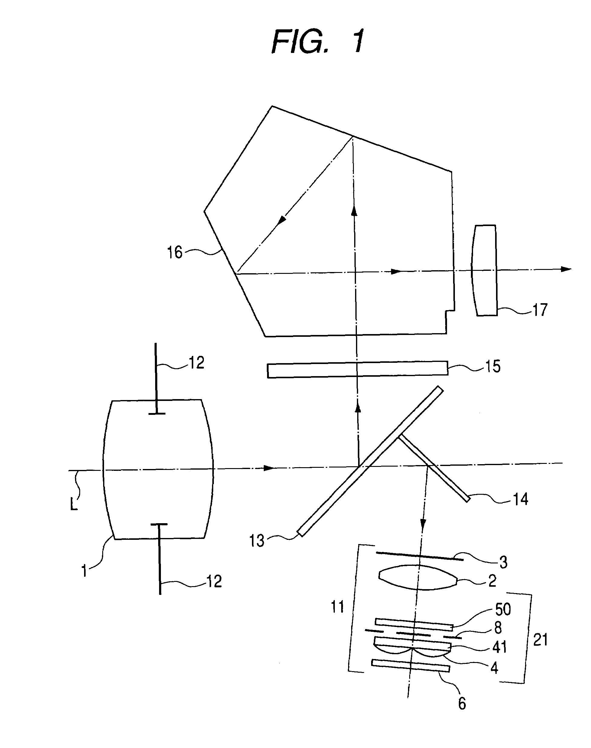
[0026]FIG. 1 is a schematic configuration of a main portion of Embodiment 1 when a focus detecting apparatus of the present invention is applied to a single-lens reflex camera (optical apparatus). FIG. 2A is a cross sectional view of a main portion of a focus detecting system shown in FIG. 1 when viewed from a certain viewpoint, and FIG. 2B is a cross sectional view of the main portion of the focus detecting system shown in FIG. 1 when viewed from a direction perpendicular to the direction in FIG. 2A.

[0027]In those figures, reference numeral 1 designates a detachable or fixed objective lens (photographing lens), reference numeral 12 designates a pupil of the objective lens 1, reference symbol L designates an optical axis of the objective lens 1, and reference numeral 13 designates a semitransmissive main mirror disposed on the optical axis L of the objective lens 1. Reference numeral 15 designates a focal plane plate on which an object image through the objective lens 1 is formed vi...

embodiment 2

[0063]FIG. 7 is a cross sectional side view of a main portion of an optical system of a focus detecting apparatus according to Embodiment 2 of the present invention. In the figure, the same constituent elements as those shown in FIG. 2 are designated with the same reference numerals.

[0064]A difference of Embodiment 2 from Embodiment 1 described above is that a diffraction optical element 43 is used as color misregistration correcting means, and the diffraction optical element 43 is formed on a light beam incidence surface of a prism 42 integrated with a secondary image forming lens 44. Other configurations and optical operations are nearly the same as those of Embodiment 1, and thus the same effects can be obtained.

[0065]That is, in the figure, reference numeral 71 designates a secondary image forming optical system including: image forming means 44 for separating an object image based on a plurality of light quantity distributions into two object images in a correlation direction t...


PUM


Abstract

Disclosed is a focus detecting apparatus which is capable of enlarging a focus detection region and of enhancing focus detection precision. The focus detecting apparatus includes a secondary image forming optical system for forming a plurality of light, quantity distributions related to an object image from light beams passed through different pupil regions of an objective lens, and a photoelectric transducer having a plurality of pixel lines each having a plurality of pixels aligned in a predetermined direction, each of the plurality of light quantity distributions being formed on a corresponding pixel lines of the plurality of pixel lines. The secondary image forming optical system includes a deflecting member for deflecting at least one of the plurality of light quantity distributions in a direction perpendicular to the predetermined direction, and a correcting member for correcting displacement of an image formation position in the deflection direction of the deflecting member due to wavelength dependency.

Description

BACKGROUND OF THE INVENTION[0001]1. Field of the Invention[0002]The present invention relates to a focus detecting apparatus which is suitable for, for example, focus detection of a photographing lens of a single-lens reflex camera or the like.[0003]2. Related Background Art[0004]In recent years, many photographing cameras or video cameras have built-in focus detecting apparatuses for automatic focus adjustment. In focus detecting apparatuses, such as a single-lens reflex camera, each requiring severe focus precision, a focus detecting apparatus using a so-called image blurring method (phase difference detecting method) is generally used (refer to Japanese Patent Application Laid-Open No. 2001-66496 for example).[0005]FIG. 8 is a cross sectional view of a main portion of a conventional focus detecting apparatus using an image blurring method of this sort.[0006]In the figure, reference symbol ο designates an object plane (subject plane), reference numeral 81 designates an objective l...

Claims


Application Information

Patent Timeline
Patent Type & Authority Patents(United States)
IPC IPC(8): G02B7/28G03B13/18G02B5/04G03B13/36G02B7/34G03B13/00H04N5/232
CPCG02B7/34
Inventor OHMURA, YUSUKE
Owner CANON KK
Why Eureka
Try Eureka