
Procedure for driving a moveable part of an item of furniture

Inactive Publication Date: 2007-10-16
JULIUS BLUM GMBH
View PDF24 Cites 35 Cited by
  • Summary
  • Abstract
  • Description
  • Claims
  • Application Information

AI Technical Summary

Benefits of technology

[0013]By means of this electronic uncoupling of the drive unit there is obtained both a simple operating control of the moveable part and an improvement in the standard of safety. Since the force exerted by the drive unit on the moveable part just compensates the forces opposing the movement of the moveable part, the user can exercise manual input (for example by pushing or pulling) on the moveable part to obtain the speed of movement which is desired. The user is not tied to a predetermined selection but can select any desired speed of movement. Provision is naturally made for a maximal level of selected speed options and also for the selection of selectable speeds to be governed by safety considerations.
[0017]Even if a collision between the moveable part and an object does occur, the electronic decoupling of the drive unit in accordance with the invention is advantageous compared with simply switching off the drive unit after the initial acceleration phase because the drive unit is immediately available to react to a detected-collision, and here immediately signifies without the time-delay necessitated by switching on the drive unit which is unavoidable under the state of the technology.

Problems solved by technology

Under the state of the technology, powered moveable parts also have the disadvantage that the speed of the moveable parts can only be controlled by the user to a limited extent, if at all, Even when it is possible to select from a choice of predetermined nominal speeds that is achieved in a most unintuitive manner by the activation of switch elements.

Method used


Image

  • Procedure for driving a moveable part of an item of furniture
  • Procedure for driving a moveable part of an item of furniture
  • Procedure for driving a moveable part of an item of furniture

Examples


Embodiment Construction

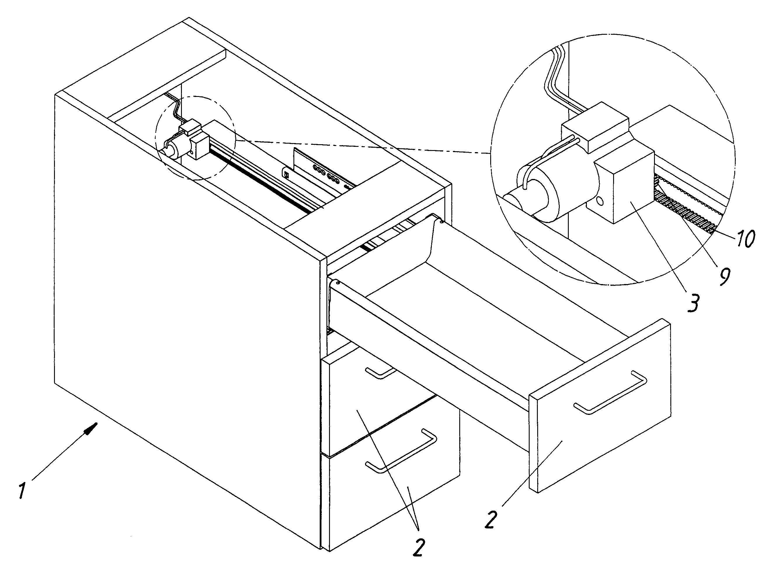
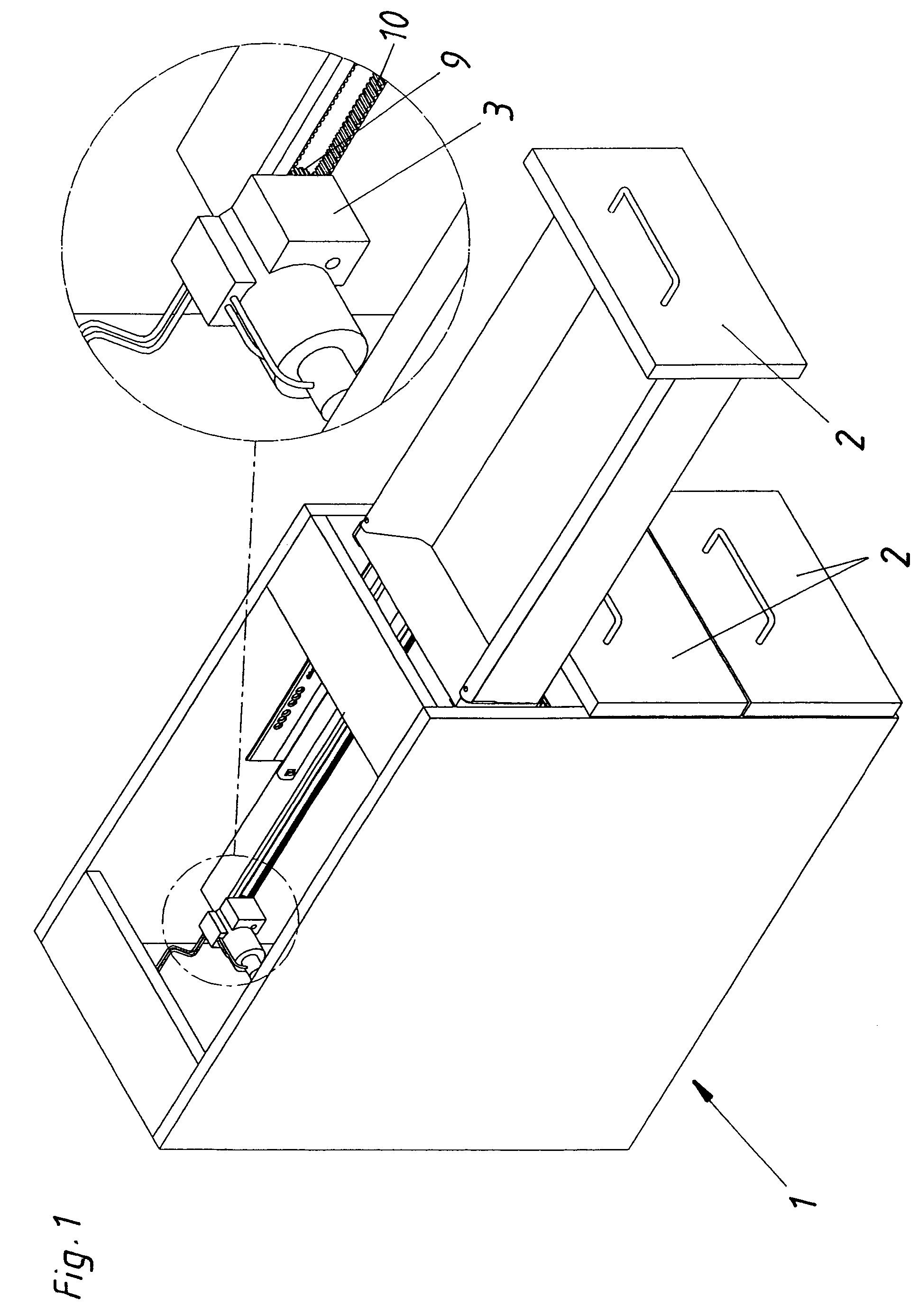
[0033]FIG. 1 displays in schematic form an item of furniture 1 with several moveable parts 2, where the upper moveable part 2 is depicted in a drawn-out position. A drive unit 3, which in this particular embodiment is an electric motor, is shown in the detailed representation together with a roller 9 over which passes a toothed belt 10. The drive unit 3 drives the roller 9 and, consequently, the toothed belt 10. By means of the toothed belt 10, the moveable part 2 is moved in a known manner. In the example depicted in FIG. 1 the drive unit 3 includes a measurement device (not shown) for the electric current to determine in accordance with the invention the force exerted on the moveable part 2 by the drive unit 3.

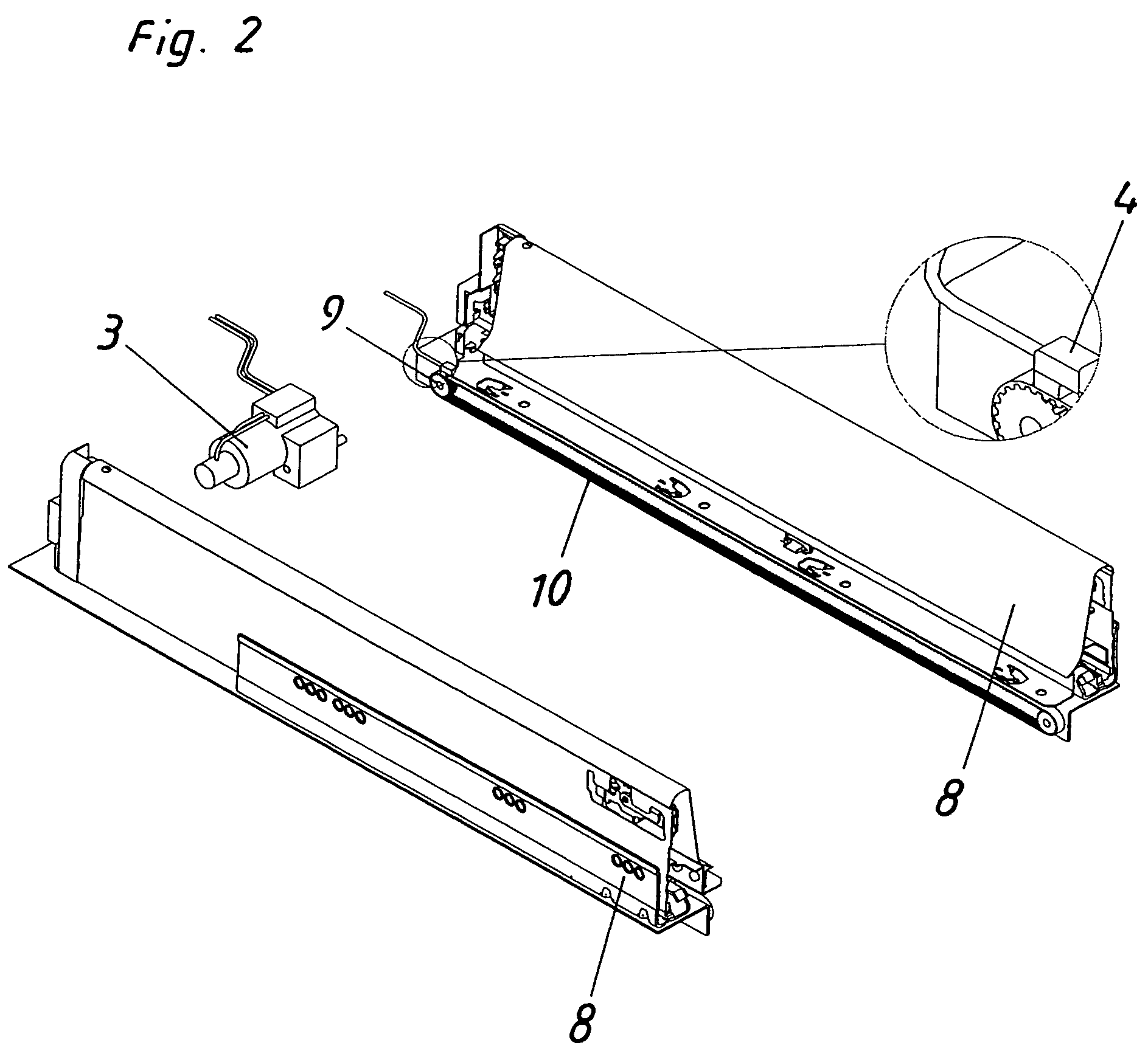
[0034]The embodiment example shown in FIG. 2 differs from that of FIG. 1 in that the determination of the force is not carried out by current measurement device integrated in the drive unit 3 but rather by a mechanical force sensor 4 which is in contact with the toothed belt...


PUM


Abstract

A method of driving a moveable part and, in particular, a drawer by a drive unit and, in particular, an electric drive unit. At least over a partial length of track (S2), forming part of the total track traversed by the moveable part, the force exerted on the moveable part by the drive unit is controlled at a predetermined level.

Description

[0001]This application is a continuation of International application PCT / AT2004 / 000148, filed May 3, 2004.BACKGROUND OF THE INVENTION[0002]1. Technical Field[0003]The present invention relates to a method of driving a moveable part of an item of furniture and, in particular, a drawer, by means of, in particular, an electrically-powered drive unit.[0004]2. Related Art[0005]In the case of moveable parts in an item of furniture, there is a possible risk of injury to the user even when the moveable part of the item of furniture is not moved by a power source. Also, damage to the moveable part can be caused by the movable part colliding with an object in the travel path of the moveable part. Therefore, an attempt was made within the state of the technology to eliminate this danger by using the widest range of safety measures, all of which have the disadvantage that the manufacturing costs of the item of furniture are increased.SUMMARY OF THE INVENTION[0006]It is the object of the presen...

Claims


Application Information

Patent Timeline
IPC IPC(8): G05D15/00A47B88/04
CPCA47B88/0414E05F15/643E05Y2900/20A47B88/457
Inventor HUBER, EDGARSCHEFFKNECHT, UWE
Owner JULIUS BLUM GMBH
Learn More