Projection lens and projection display device using the same

a projection display device and projection lens technology, applied in the field of projection lenses, can solve the problems of difficult simultaneous satisfaction of all of the various demands described above, insufficient field angle and back focus, and difficult distortion correction, and achieve the effects of low cost, favorable correction of aberrations, and simple construction

Inactive Publication Date: 2007-10-09
FUJI PHOTO OPTICAL CO LTD
View PDF12 Cites 11 Cited by
  • Summary
  • Abstract
  • Description
  • Claims
  • Application Information

AI Technical Summary

Benefits of technology

[0011]The present invention relates to a wide-angle projection lens that enables arranging a mirror as the optical path deflector, has a construction suitable for miniaturization, favorably corrects aberrations, especially distortion, has a simple construction, and is lightweight and of low cost. The present invention further relates to a projection display device using such a projection lens.

Problems solved by technology

However, a projection lens for high correction of distortion is particularly required so that the seams of each unit are not strikingly evident in a large picture, which requires distortion to be kept within 0.3%.
Generally, the front and rear lens groups on opposite sides of a stop in a wide-angle projection lens are highly asymmetrical, which makes distortion correction particularly difficult.
As described above, many projection lenses for miniaturizing a cabinet projection display device have been proposed, but simultaneously satisfying all of the various demands described above is very difficult.
The projection lens described in Japanese Laid-Open Patent Application 2001-337267 has an insufficient field angle and an insufficient back focus, and also has a large number of lens elements.
The projection lens described in Japanese Laid-Open Patent Application 2002-031754 does not provide a small enough f-number.
The projection lens described in Japanese Laid-Open Patent Application 2003-195164 has insufficient field angles and does not provide a small enough f-number.
The projection lens described in Japanese Laid-Open Patent Application 2003-156683 is suitable for miniaturization because it provides a wide field angle and the optical path is deflectable at an acute angle in the lens system, but the use of the lens is limited because the back focus is short and distortion is great.
The projection lens described in Japanese Laid-Open Patent Application 2003-248169 is suitable for miniaturization because a prism is arranged to deflect the optical path in the lens system, but this is less favorable than a mirror in terms of weight and cost.
Therefore, a mirror cannot simply replace the prism.
Although a mirror provides advantages of less weight and lower cost than a prism, a larger space must be provided, which increases the difficulty of optical design as compared to using a prism.

Method used


Image

  • Projection lens and projection display device using the same
  • Projection lens and projection display device using the same
  • Projection lens and projection display device using the same

Examples


embodiment 1

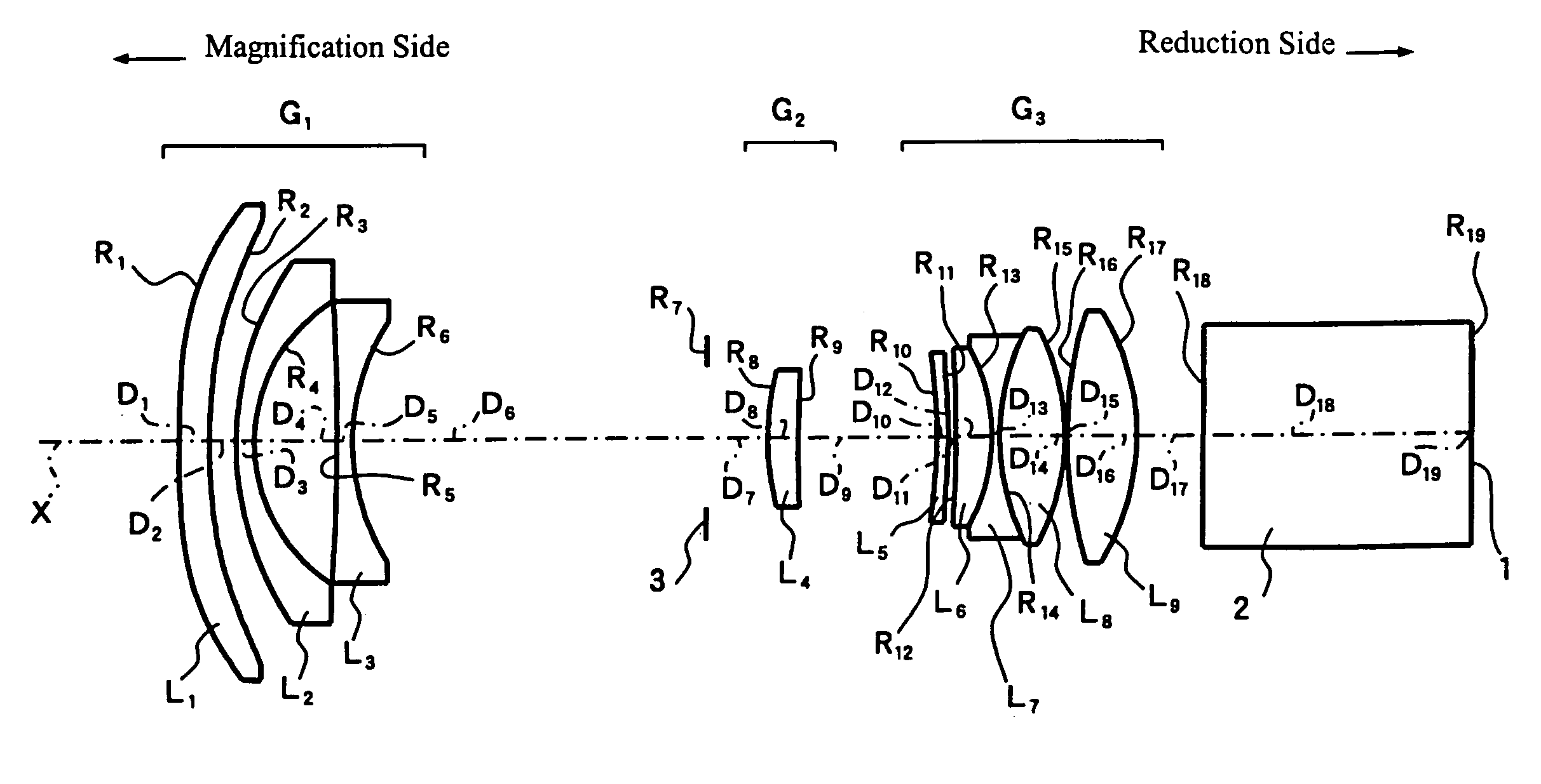
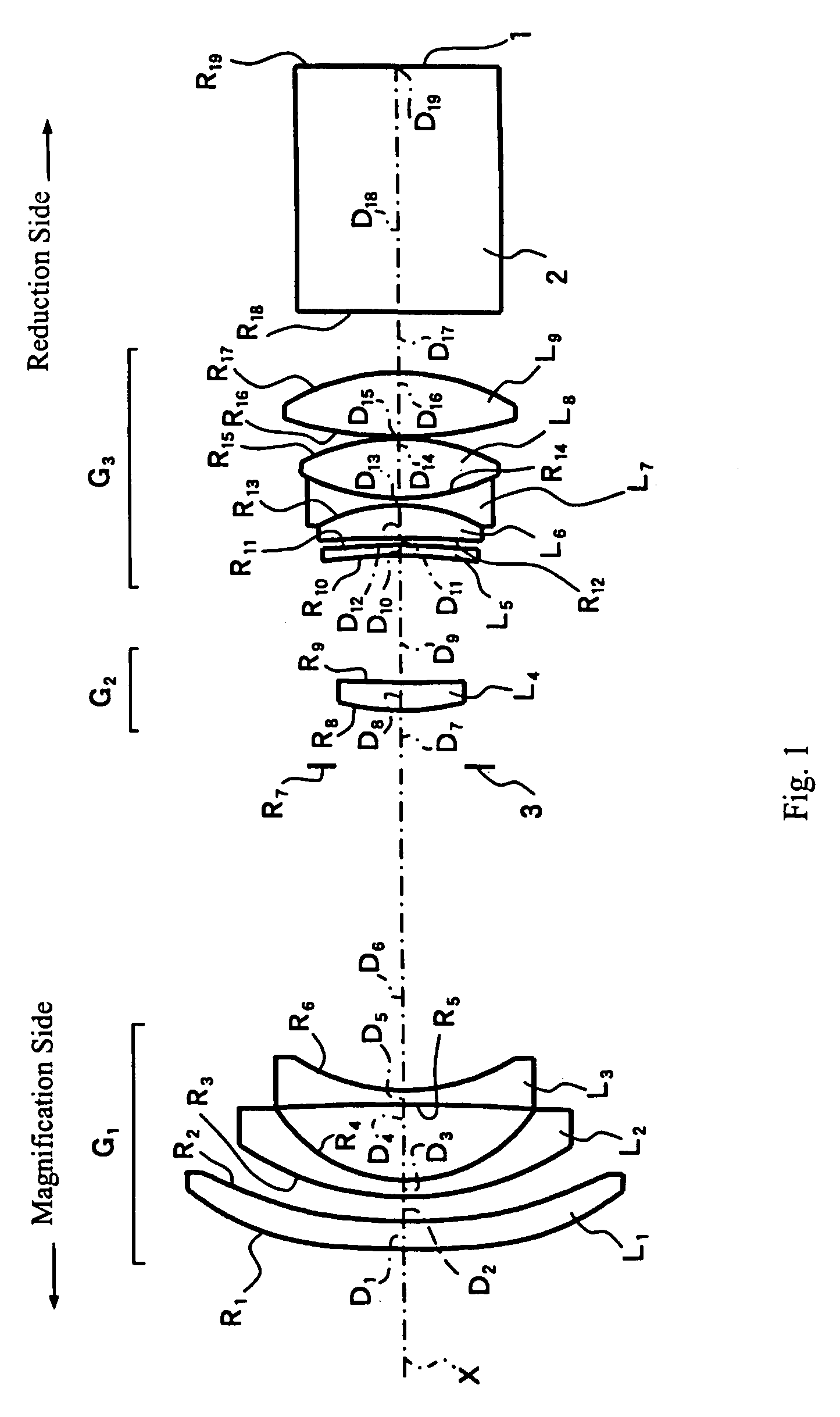
[0069]FIG. 1 shows a cross-sectional view of the projection lens of Embodiment 1 of the present invention. As shown in FIG. 1, the projection lens of Embodiment 1 includes, arranged in order from the magnification side, a first lens group G1 that includes a first lens element L1 having negative refractive power, a meniscus shape, a convex surface on the magnification side, and two aspheric surfaces, a second lens element L2 having negative refractive power, a meniscus shape, and a concave surface on the reduction side, and a third lens element L3 having a biconcave shape and with its surface having the greater absolute value of refractive power on the reduction side.

[0070]The second lens group G2 includes a fourth lens element L4 having positive refractive power, a meniscus shape, and a convex surface on the magnification side.

[0071]The third lens group G3 includes a fifth lens element L5 of positive refractive power and meniscus shape with its convex surface on the reduction side a...

embodiment 2

[0082]FIG. 4 shows a cross-sectional view of the projection lens of Embodiment 2 of the present invention. The construction of this projection lens is roughly the same as the projection lens of Embodiment 1, but the construction of the third lens group G3 is different.

[0083]The third lens group G3 of the projection lens of Embodiment 2 includes, arranged in order from the magnification side: a fifth lens element L5 of positive refractive power and meniscus shape with its convex surface on the reduction side and both surfaces aspheric; a lens component formed by cementing together a sixth lens element L6 of biconvex shape having surfaces of different curvature with its surface of greater absolute value of refractive power being on the reduction side and a seventh lens element L7 of biconcave shape having surfaces of different curvature with the surface of greater absolute value of refractive power being on the magnification side; an eighth lens element L8 of biconvex shape having sur...

embodiment 3

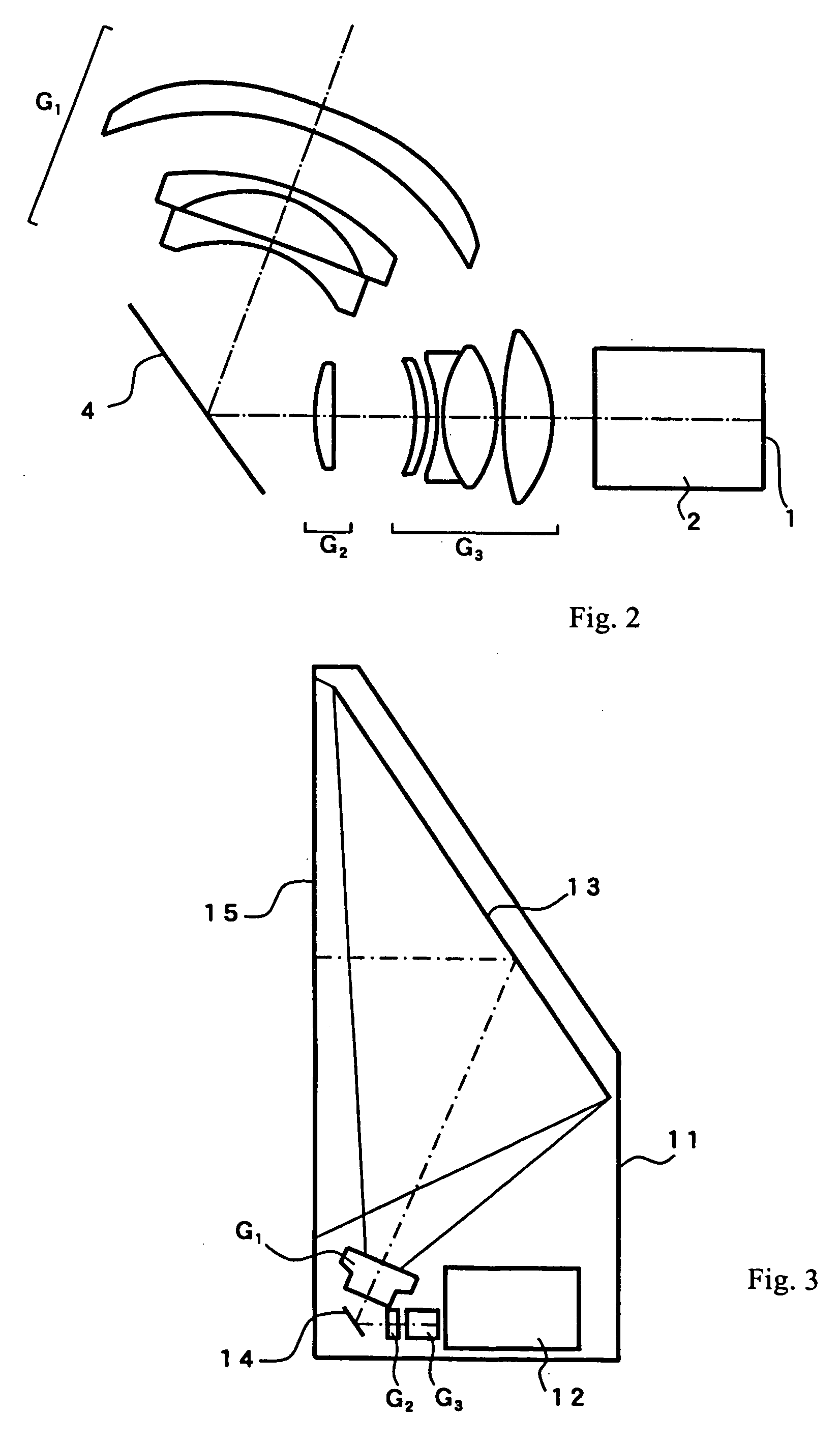
[0096]FIG. 5 shows a cross-sectional view of the projection lens of Embodiment 3 of the present invention. The construction of this projection lens is roughly the same as the projection lens of Embodiment 1 but is different in that the position of the aperture stop is not shown. This projection lens has a space sufficient for a mirror for deflecting the optical path between the first lens group G1 and the second lens group G2 in a manner similar to that shown in FIG. 2 with regard to the mirror 4. This projection lens is constructed so as to be telecentric on the reduction side; therefore it is also suitable for a construction with glass block 2 operating as a color synthesizer.

[0097]Table 7 below lists the surface number # in order from the magnification side, the radius of curvature R of each surface on the optical axis, the on-axis surface spacing D, as well as the refractive index Nd and the Abbe number νd (both at the d-line of 587.6 nm) of each optical element for Embodiment 3...


PUM


Abstract

A projection lens includes three lens groups, arranged as follows from the magnification side: a first lens group of negative refractive power, a second lens group of positive refractive power, and a third lens group of positive refractive power. The first lens group includes three lens elements, each of negative refractive power, and two of these lens elements each have a meniscus shape with its convex surface on the magnification side. The second lens group includes a lens element having positive refractive power, a meniscus shape, and a convex surface on the magnification side. The third lens group includes: a lens element of positive refractive power and a meniscus shape with its convex surface on the reduction side; a cemented lens component; and at least one aspheric surface. The projection lens satisfies specified conditions regarding focal lengths and spacings of lens surfaces. A projection display device uses the projection lens.

Description

FIELD OF THE INVENTION[0001]The present invention relates to a projection lens for magnifying and projecting display information on light valves, and in particular, relates to a projection lens suitable for a rear projection display device, such as rear projection televisions and similar display devices.BACKGROUND OF THE INVENTION[0002]Known projection display devices include front projection display devices in which a projection lens is arranged on the same side as an audience viewing light beams containing information reflected from a reflective display screen, and rear projection display devices in which a transmissive display screen is arranged between an audience and a projection lens that transmits light beams containing information to the transmissive display screen. In rear projection display devices, such as rear projection televisions, it is well known to arrange the transmissive display screen in the front of a cabinet that contains a light source and the projection lens ...

Claims


Application Information

Patent Timeline
Patent Type & Authority Patents(United States)
IPC IPC(8): G02B15/14
CPCG02B13/16
Inventor NAGAHARA, AKIKOYAMAMOTO, CHIKARA
Owner FUJI PHOTO OPTICAL CO LTD
Why Eureka
Try Eureka