
Apparatus and method for controlling convergence of projection television

a technology of projection television and convergence, applied in the field of image display devices, can solve the problems of poor luminance of a marginal portion of the screen and poor luminance of a central portion, and achieve the effect of improving the image classification rate of a ccd camera and uniform luminance level

Inactive Publication Date: 2007-10-09
SAMSUNG ELECTRONICS CO LTD
View PDF16 Cites 0 Cited by
  • Summary
  • Abstract
  • Description
  • Claims
  • Application Information

AI Technical Summary

Benefits of technology

The present invention provides an apparatus and method for controlling the convergence of a projection television. The apparatus generates video patterns to control the convergence and adjusts their luminance levels to match those of reference patterns. This allows for a more uniform luminance level and improves the image classification rate of a CCD camera. The method also allows for the luminance levels of video patterns in random positions on the screen to be controlled. The invention provides an improved means of controlling the convergence of a projection television to enhance the image quality of the displayed images.

Problems solved by technology

Also, the luminance of a marginal portion of the screen is poorer than the luminance of a central portion of the screen.

Method used


Image

  • Apparatus and method for controlling convergence of projection television
  • Apparatus and method for controlling convergence of projection television
  • Apparatus and method for controlling convergence of projection television

Examples


Embodiment Construction

[0025]Reference will now be made in detail to the illustrative, non-limiting embodiments of the present invention, examples of which are illustrated in the attached drawings wherein like reference numerals refer to like elements throughout. The exemplary embodiments are described below in order to explain the present invention by referring to the figures.

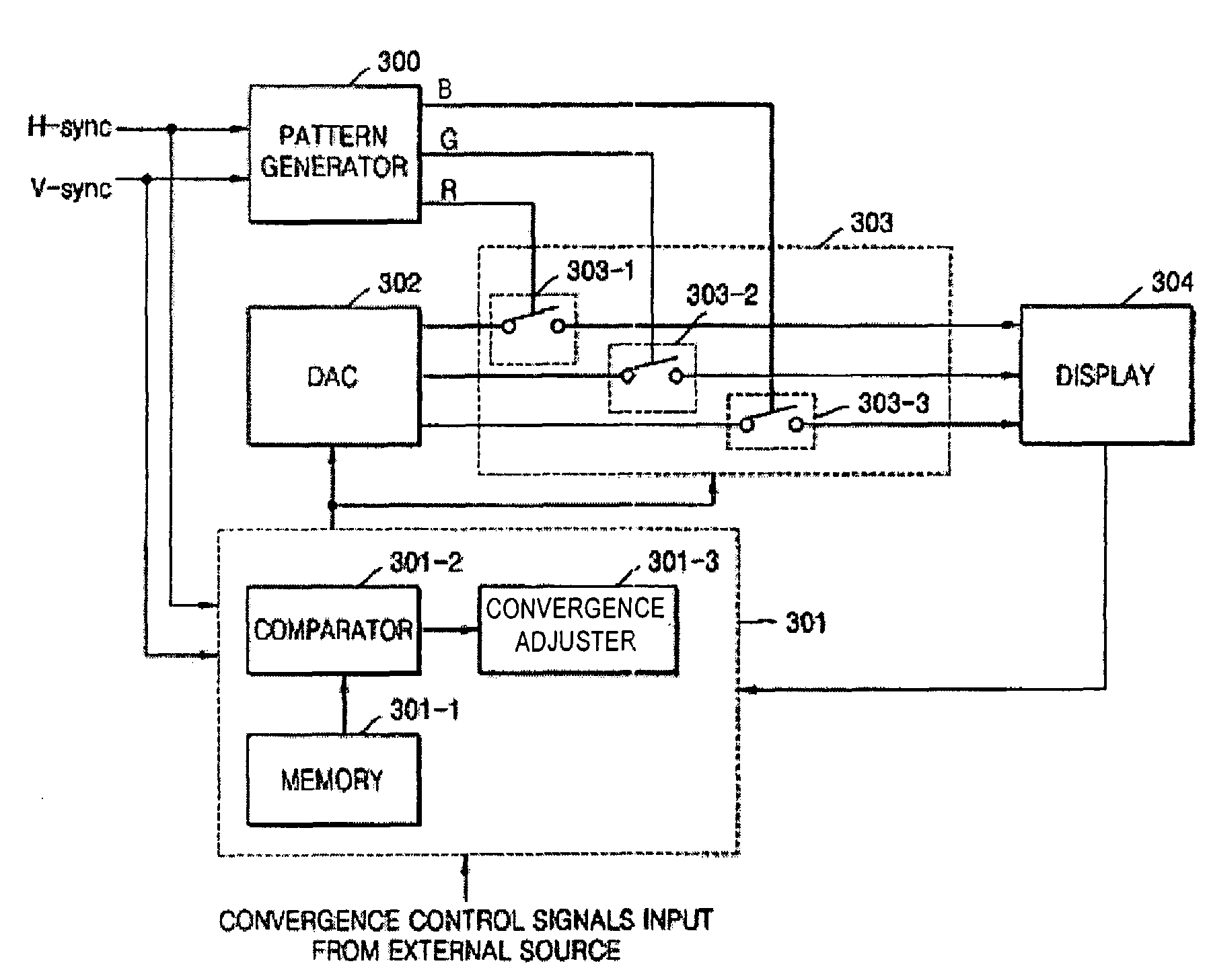
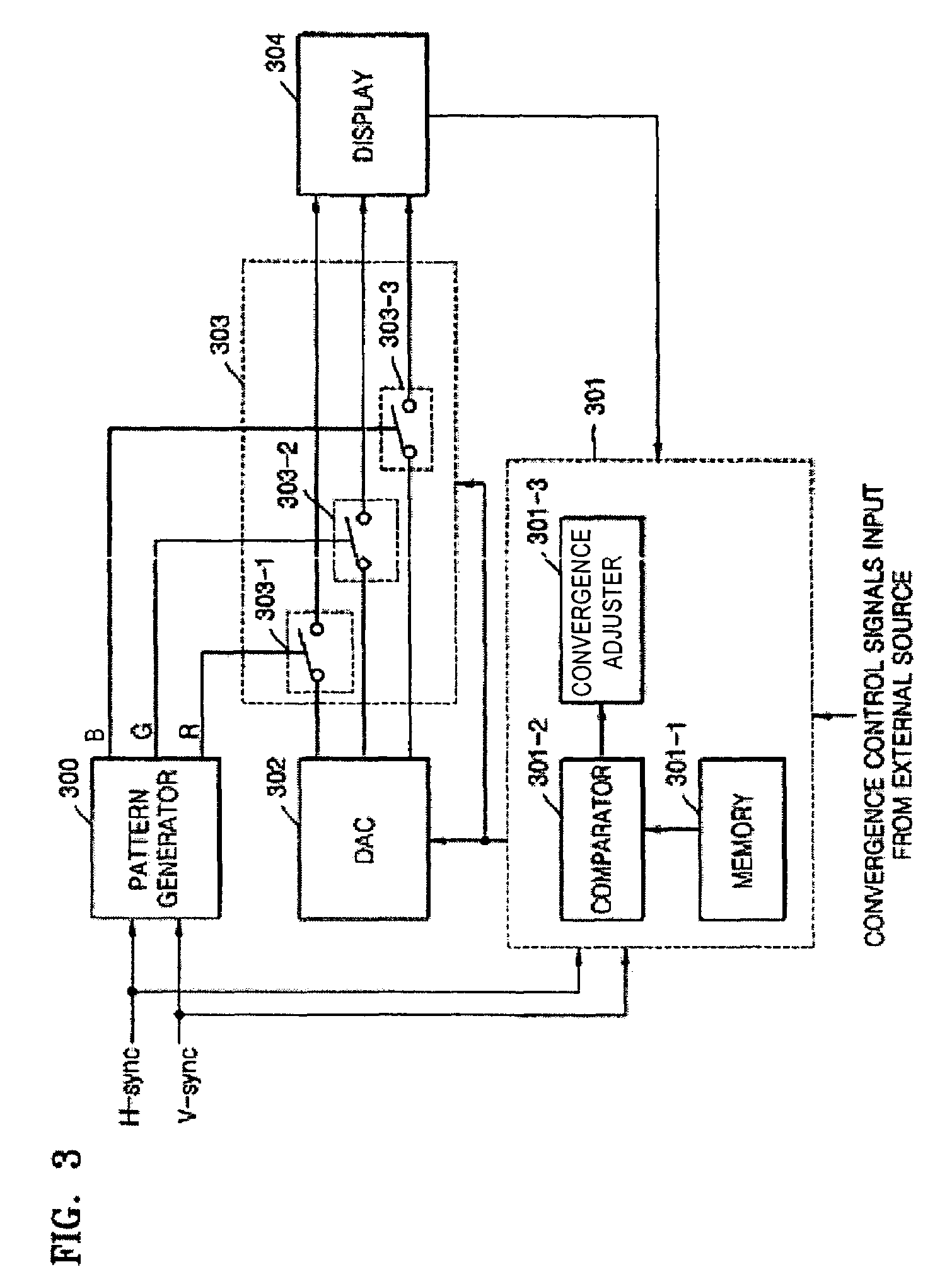
[0026]FIG. 3 is a block diagram of an apparatus for controlling a convergence of a projection television, according to the present invention. Referring to FIG. 3, the apparatus includes a pattern generator 300, a controller 301, a digital-to-analog converter (DAC) 302, a switching unit 303, and a display 304. The controller 301 includes a memory 301-1, a comparator 301-2, and a convergence adjuster 301-3. The switching unit 303 includes first, second, and third switches 303-1, 303-2, and 303-3.

[0027]FIG. 4 is a flowchart for explaining a process of generating video patterns used for controlling a convergence of a projection televisi...


PUM


Abstract

An apparatus and method for controlling a convergence of a projection television includes a pattern generator which generates R, G, and B video patterns used for controlling the convergence and then outputs the R, G, and B video patterns to a display, and a controller which compares position coordinates and luminance levels of the R, G, and B video patterns with position coordinates and luminance levels of reference R, G, and B video patterns to adjust the luminance levels of the R, G, and B video patterns to the luminance levels of the reference R, G, and B video patterns.

Description

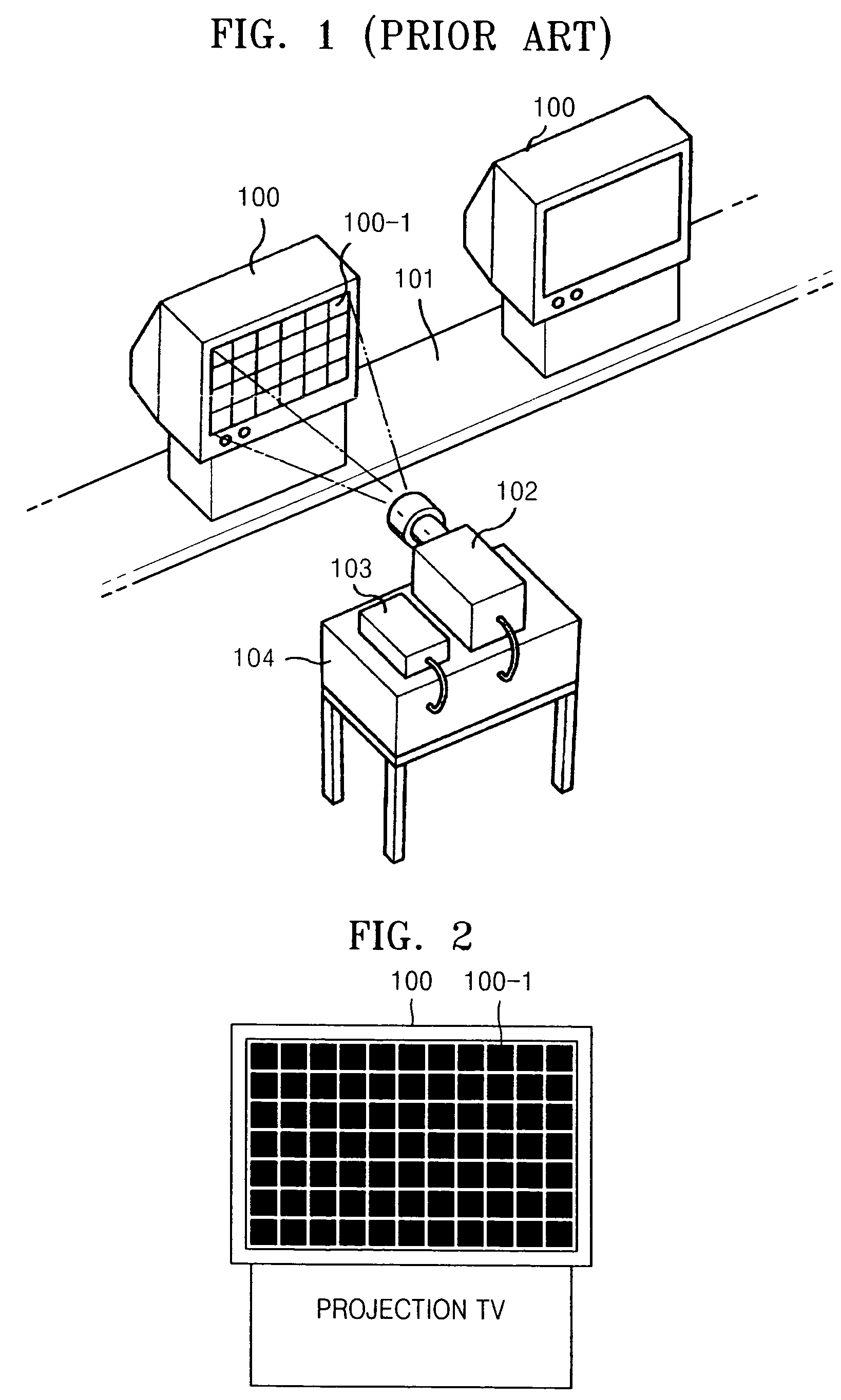
BACKGROUND OF THE INVENTION[0001]This application claims the priority of Korean Patent Application No. 2003-38518, filed on Jun. 14, 2003, in the Korean Intellectual Property Office, the disclosure of which is incorporated herein in its entirety by reference.[0002]1. Field of the Invention[0003]An apparatus and method consistent with the present invention relates to operating an image display device, and more particularly, to an apparatus and a method for controlling a convergence of a projection television in which video patterns used for controlling the convergence can be generated so as to allow the projection television to have an overall uniform luminance level, and luminance levels of the video patterns in random positions of the projection television can be freely controlled.[0004]2. Description of the Related Art[0005]A projection television includes R (red), G (green), and B (blue) cathode ray tubes (CRTs) which display R, G, and B color images to project the R, G, and B co...

Claims


Application Information

Patent Timeline
Patent Type & Authority Patents(United States)
IPC IPC(8): H04N3/22H04N3/223H04N5/74H04N9/28H04N9/31H04N17/00H04N17/04
CPCH04N9/28H04N17/04H04N9/31H04N5/74
Inventor RYU, IL-GYEONSHIM, JAE-SEUNG
Owner SAMSUNG ELECTRONICS CO LTD
Learn More