
Steering system with haptic driver warning

a technology of steering system and driver warning, which is applied in the direction of repeater circuit, line-transmission details, instruments, etc., can solve the problems of perceived vibration indistinguishable mechanical vibration generated in the steering wheel,

Active Publication Date: 2007-10-09
GM GLOBAL TECH OPERATIONS LLC +1
View PDF11 Cites 40 Cited by
  • Summary
  • Abstract
  • Description
  • Claims
  • Application Information

AI Technical Summary

Benefits of technology

The invention is a steering column assembly and method for alerting a driver to an emergency condition in a vehicle. The assembly includes a steering column with a free end and a steering axis extending from the free end. A steering wheel is secured to the free end of the steering column for manual rotation by a driver in a perpendicular plane to the steering axis. A sensor detects the occurrence of an emergency condition and a haptic controller automatically moves the rotation plane of the steering wheel in rapid short reversing directions to alert the driver to the emergency. The sudden movement of the steering wheel creates an unusual sensation for the driver, prompting them to address the emergency condition immediately. The invention helps to focus driver attention on the emergency and can be distinguished from normal occurring vibrations in non-emergency situations.

Problems solved by technology

A particular disadvantage of these prior art systems for motor vehicles resides in the fact that the mechanical vibrations generated in the steering wheel are often indistinguishable from normally occurring vibrations in non-emergency situations.
For example, an out of balance tire or rough road can result in perceived vibrations in the steering wheel which are indistinguishable from those created by the prior art vibrating units.

Method used


Image

  • Steering system with haptic driver warning
  • Steering system with haptic driver warning
  • Steering system with haptic driver warning

Examples


Embodiment Construction

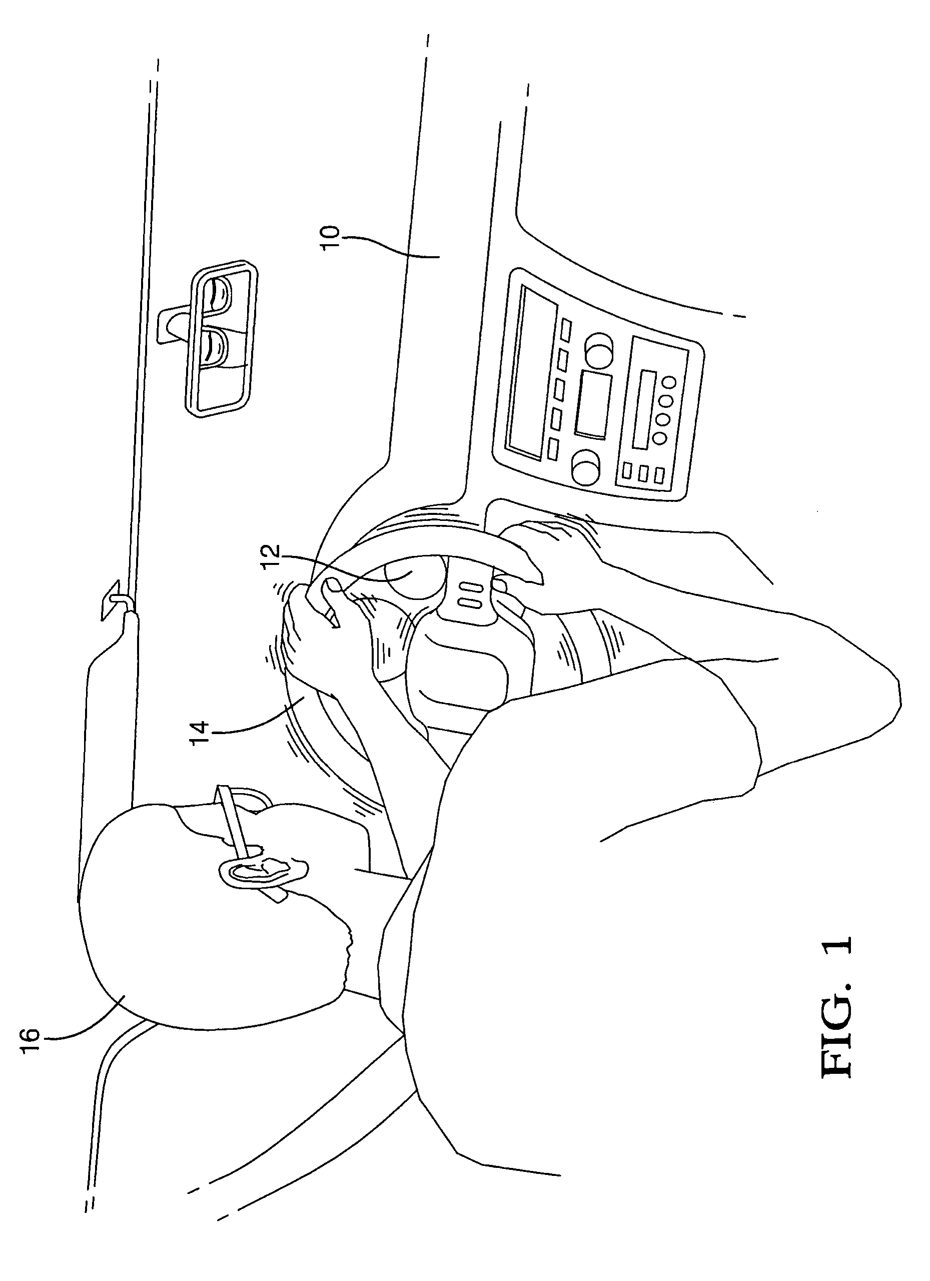
[0015]Referring to the figures wherein like numerals indicate like or corresponding parts throughout the several views, FIG. 1 illustrates a fragmentary interior perspective view of a motor vehicle including a dash board 10 with an inset instrument cluster 12. A steering wheel 14 is supported for rotation generally in front of the instrument cluster 12 and adapted to be grasped manually by a driver 16. By manually rotating the steering wheel 14, the driver 16 controls one or more steerable wheels of the vehicle.

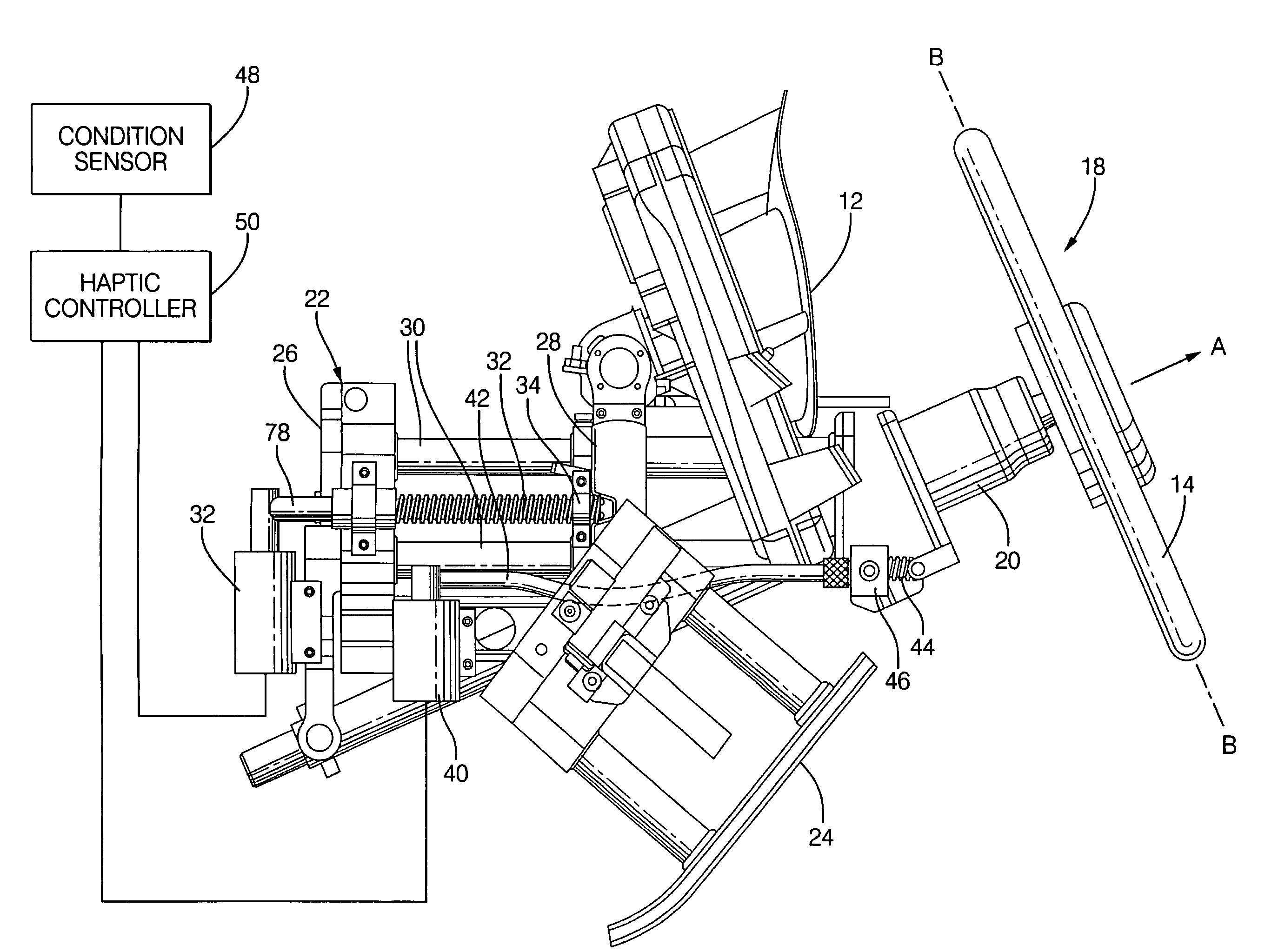
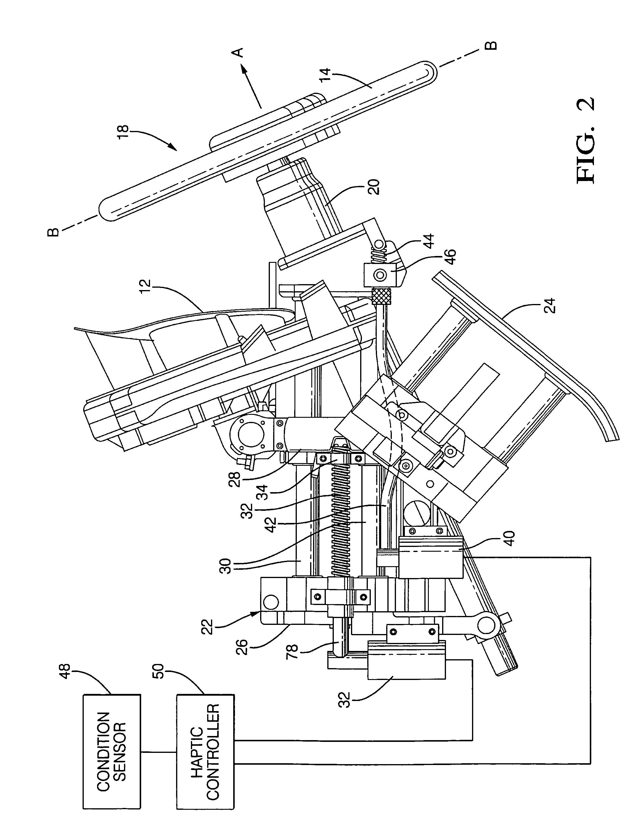
[0016]The steering wheel 14 may be supported by any number of methods and components, but is shown in FIG. 2 in one exemplary fashion. Here, a steering column assembly is generally shown at 18. The steering wheel 14, which is a component of the steering column assembly 18, is rotatably supported on the free end of a steering column 20 for rotation about a steering axis A within a generally perpendicular, or normal, geometric plane B-B. A column support, generally indicated at...


PUM


Abstract

A steering column assembly (18) of the type for controlling one or more steerable wheels in a motor vehicle includes a steering wheel (14) interface secured to the free end of a steering column (20). The steering column assembly (18) includes powered telescope adjust and tilt adjust features which a driver (16) uses to adjust the position of the steering wheel (14) for maximum comfort. One or more condition sensors (48) monitor numerous parameters about the vehicle. When an emergency condition is detected, such as the seat belt warning, a door that is ajar, various engine conditions, or erratic driving activity, a haptic controller (50) rapidly vibrates the steering wheel (14) through the telescoping and tilt adjusting motors (32, 40) as a means of alerting the driver (16) to the emergency condition. These warnings can be given priority so that a first warning is communicated by steering wheel (14) vibrations in one direction, and a second warning is communicated by vibrations in both the first direction and a second direction simultaneously. In addition, a third warning can be given emphasis by increasing the power of the vibration to a resonance mode to cause an audible warning.

Description

FIELD OF THE INVENTION[0001]This invention relates to a steering column assembly for operating a vehicle, and more particularly toward a steering column assembly and steering method for alerting a driver to an emergency condition.BACKGROUND OF THE INVENTION[0002]When operating a motor vehicle, a driver must be notified of all conditions which might jeopardize safety or affect proper operation of the vehicle. For examples, an ajar door or engine malfunction is commonly detected by a built-in sensor and the status of that condition announced by a dashboard light, message, chime, or sometimes a verbal recorded message. Upon notification, a driver can then take corrective action.[0003]In the case of motor vehicles, there have been various proposals put forward to enhance driver focus to the detection of an emergency condition. Such proposals have included the incorporation of vibrating units mounted within a steering wheel which generate mechanical vibrations perceivable by touch and ea...

Claims


Application Information

Patent Timeline
Patent Type & Authority Patents(United States)
IPC IPC(8): G08B23/00
CPCB60K28/066B60W50/16B62D15/029B62D1/181B60W2710/20B60W2040/0818B60K35/25
Inventor BERG, FREDERICK J.BENNETT, TIMOTHY J.DAVIS, ALAN C.RIEFE, RICHARD K.DYBALSKI, RONALD H.PHILLIPS, TIMOTHY M.
Owner GM GLOBAL TECH OPERATIONS LLC
Learn More