
Vehicle air handling system

a technology for handling systems and vehicles, applied in vehicle components, vehicle heating/cooling devices, transportation and packaging, etc., can solve problems such as out of reach, achieve the effects of improving the comfort of drivers or other passengers, improving side window defrosting, and improving noise reduction

Active Publication Date: 2022-01-25
NISSAN MOTOR CO LTD
View PDF10 Cites 0 Cited by
  • Summary
  • Abstract
  • Description
  • Claims
  • Application Information

AI Technical Summary

Benefits of technology

The present invention is an improved vehicle air handling system that allows the driver to control the airflow through the panel ducts for better driver comfort, side window defrosting, or noise reduction. The system has a simple and lightweight structure and can be adjusted even when there is no passenger.

Problems solved by technology

In addition, the driver may want to adjust multiple grill shutters and some may be out of reach.

Method used


Image

  • Vehicle air handling system
  • Vehicle air handling system
  • Vehicle air handling system

Examples


second embodiment

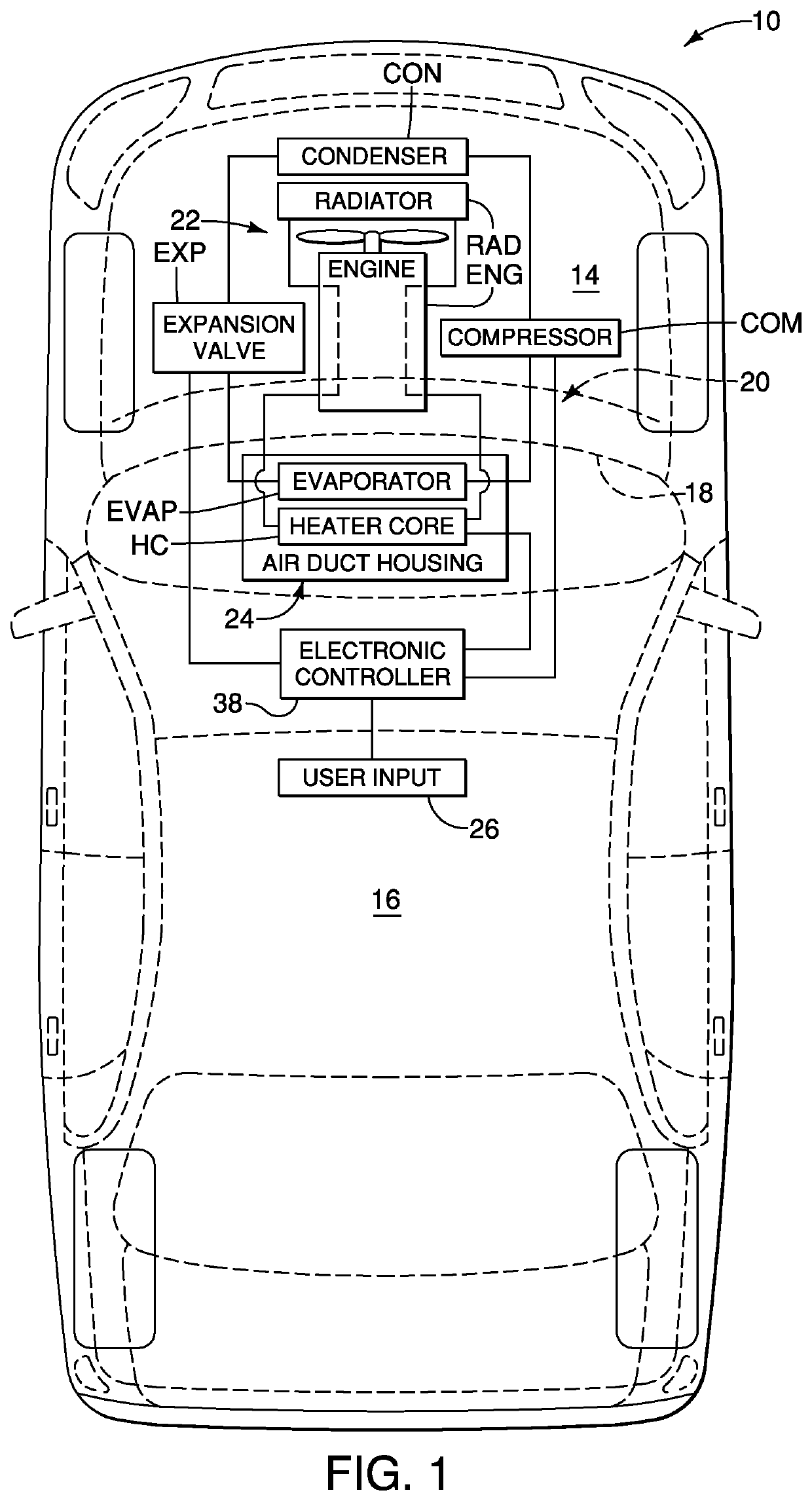
[0089]Referring now to FIGS. 38 and 39, a vehicle air handling system 12′ including an air duct housing 24′ in accordance with a second embodiment will now be explained. The vehicle air handling system 12′ of this second embodiment is identical to the air handling system 12 of the first embodiment, except that the air duct housing 24′ of this second embodiment is a modified version of the air duct housing 24 of the first embodiment. Therefore, it will be apparent to those having ordinary skill in the art from this disclosure that the descriptions and illustrations of the first embodiment also apply to this second embodiment, except as explained and illustrated herein. Moreover, parts of this second embodiment, if identified in FIGS. 37-38, that are identical to parts of the first embodiment will be given the same reference numerals for the sake of convenience. Moreover, the descriptions of the parts of the second embodiment that are identical to the parts of the first embodiment may...


PUM


Abstract

A vehicle air handling system includes a user input interface, air duct housing, first and second panel duct doors, at least one air blower, and a first panel actuation assembly. The air duct housing has an air inlet, and first and second panel ducts. The first and second panel duct doors are disposed to selectively open and close the first and second panel ducts, respectively. Air is drawn into the air duct housing via the air inlet and conveyed toward the panel ducts. The first panel actuation assembly is operatively coupled to the first and second panel duct doors to simultaneously control positions in response to operation of the user input interface between a plurality of settings. The positions of the first and second panel duct doors include at least one setting in which different airflow volumes are passed by the first and second panel duct doors.

Description

BACKGROUNDField of the Invention[0001]The present invention generally relates to a vehicle air handling system. More specifically, the present invention relates to a vehicle air handling system including panel duct doors permitting different air flow volumes to flow through panel ducts.Background Information[0002]Most vehicles include a climate control system. Typical climate control systems include a heating, ventilation and air conditioning unit that includes at least one air blower for moving air through an air circulation network. Typical climate control systems allow passengers of the vehicle to select between a heating state and a cooling state for the vehicle interior. In addition, air flow between floor ducts, panel ducts and defrost ducts can be selected. Two or three mode doors can be used to switch the air flow between floor, panel, defrost, and bilevel modes. When air is flowing through the panel ducts air flows equally through the panel ducts. FIG. 40 illustrates a Prio...

Claims


Application Information

Patent Timeline
Patent Type & Authority Patents(United States)
IPC IPC(8): B60H1/00
CPCB60H1/00842B60H1/00871B60H1/00857B60H1/00742
Inventor SOTO INFANTE, AMILKAR
Owner NISSAN MOTOR CO LTD
Learn More