Optical data recording method
a technology of optical data and recording film, applied in the field of optical data recording film, can solve the problems of serious degradation of signal quality, inability to apply predetermined quantity of heat to the recording film of the optical disc, and dull edge and falling edge of pulses in luminous waveforms
- Summary
- Abstract
- Description
- Claims
- Application Information
AI Technical Summary
Benefits of technology
Problems solved by technology
Method used
Image
Examples
embodiment 1
[0070]FIG. 3 is a block diagram showing Embodiment 1 of a data recording device according to the present invention. As shown in FIG. 3, a data recording device 100 comprises a spindle motor 102, an optical head 103, a light beam control section 104, a servo section 105, a reproduction binarizing section 106, a digital signal processing section 107, a recording compensating section 108, and a CPU 109. The light beam control section 104 and the recording compensating section 108 form a recording pulse train generating section.
[0071]An optical disc 101 is placed on the spindle motor 102 and the spindle motor 102 rotates the optical disc 101. The optical disc 101 has one or more tracks for recording data. The tracks are shaped like spirals or concentric circles. The optical disc 101 has a recording film melted by heating. When a light beam of a semiconductor laser is emitted which is modulated based on data to be recorded, a phase change occurs on a part irradiated with the light beam o...
embodiment 2
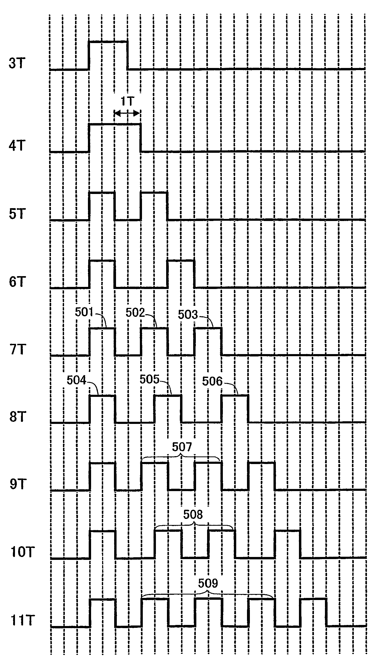
[0142]As described in Embodiment 1, by equalizing the number of pulses in each multi-pulse train of recording pulse trains 2nT and (2n+1)T or recording pulse trains (2n−1)T and 2nT, the two recording pulse trains may be different from each other in laser irradiation power. This is because a duty of a mark / space or an average value is different between the multi-pulse trains.
[0143]FIGS. 18A and 18B show recording marks and reproduction signals obtained from the formed recording marks. The recording marks are formed by a recording pulse train 2 for forming a mark 9T of FIG. 10 and a recording pulse train 8 for forming a mark 10T.
[0144]As shown in FIG. 18A, in the recording pulse train 2, a first pulse 9 and a last pulse 10 each have a pulse width of 1T and supplies mark forming thermal energy suitable for a recording film of an optical disc. Thus, a recording mark 4 to be formed has an almost even width and a reproduction signal 6 is almost shaped like a trapezoid with a mark center n...
PUM
 Abstract
Description
Claims
Application Information
 - R&D
- Intellectual Property
- Life Sciences
- Materials
- Tech Scout
- Unparalleled Data Quality
- Higher Quality Content
- 60% Fewer Hallucinations
Browse by: Latest US Patents, China's latest patents, Technical Efficacy Thesaurus, Application Domain, Technology Topic, Popular Technical Reports.
© 2025 PatSnap. All rights reserved.Legal|Privacy policy|Modern Slavery Act Transparency Statement|Sitemap|About US| Contact US: help@patsnap.com


