Projector, projection method and storage medium in which projection method is stored
a projection method and projector technology, applied in the field of projectors, can solve the problems of affecting the performance of the projector, affecting the quality of the projector, and requiring labor hours to correct the distortion of the projected image,
- Summary
- Abstract
- Description
- Claims
- Application Information
AI Technical Summary
Benefits of technology
Problems solved by technology
Method used
Image
Examples
first embodiment
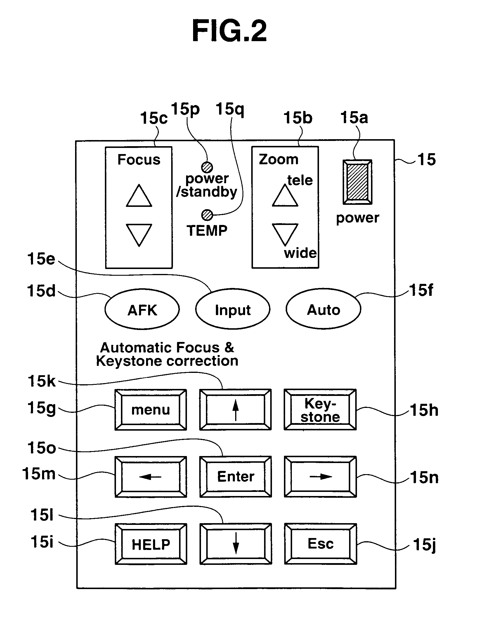
[0078]Next, the operation of the projector 10 according to a first embodiment will be described. In the first embodiment, a keystone distortion correction is implemented to a projected image by manually operating the keys.
[0079]FIG. 6 shows a flowchart explaining a keystone distortion correction according to the first embodiment. FIG. 7 shows an example of each of the status of an image adjustment menu, deformed image and projected image corresponding to each operation according to the first embodiment. Deformed images in FIG. 7 are such as to explain outlines of images projected from the projector 10 and deformations made thereto, and projected images represent outlines of images which are actually projected on to the screen and changes in outlines which occur when the deformations shown by the deformed images are made.
[0080]Firstly, when an execution of keystone distortion correction is required by operating the “Keystone” key 15h, the control unit 39 sends out image data of the i...
second embodiment
[0102]Next, the operation of the projector 10 according to a second embodiment will be described. In the second embodiment, it is made possible to implement a keystone distortion correction on a projected image through not only a manual key operation such as described in the first embodiment but also an automatic operation.
[0103]FIG. 8 shows a flowchart which describes a keystone distortion correcting process according to the second embodiment. FIG. 9 shows an example of each of the status of an image adjustment menu, deformed image and projected image corresponding to each operation according to the second embodiment.
[0104]Firstly, when the execution of a keystone distortion correction is required through the operation of the “Keystone” key 15h, the control unit 39 sends out image data of the image adjustment menu for keystone distortion correction to the display encoder 33 so as to be projected on to the screen through the control of the display drive unit 35 (Step B1).
[0105]As sh...
third embodiment
[0118]Next, the operation of the projector 10 according to a third embodiment will be described. In the third embodiment, the rotation of a projected image can be corrected by changing the set condition of the projector 10 through extension or contraction of the adjustment leg portions 22 in response to the manual operation of the keys.
[0119]FIG. 10 shows a flowchart describing a keystone distortion correcting process according to the third embodiment. FIG. 11 shows an example of each of the status of an image adjustment menu, deformed image and projected image corresponding to each operation according to the third embodiment.
[0120]Firstly, when the execution of a keystone distortion correction is required through the operation of, for example, the “Keystone” key 15h, the control unit 39 sends out image data of the image adjustment menu for keystone distortion correction to the display encoder 33 so as to be projected on to the screen through the control of the display drive unit 35...
PUM
 Abstract
Description
Claims
Application Information
 - R&D
- Intellectual Property
- Life Sciences
- Materials
- Tech Scout
- Unparalleled Data Quality
- Higher Quality Content
- 60% Fewer Hallucinations
Browse by: Latest US Patents, China's latest patents, Technical Efficacy Thesaurus, Application Domain, Technology Topic, Popular Technical Reports.
© 2025 PatSnap. All rights reserved.Legal|Privacy policy|Modern Slavery Act Transparency Statement|Sitemap|About US| Contact US: help@patsnap.com


