
Air intake system for vehicle combustion engine

a combustion engine and air intake technology, which is applied in the direction of combustion air/fuel air treatment, machines/engines, cycle equipment, etc., can solve the problems of increasing the number of component parts and the consequent increase of the manufacturing cost, and achieves the effect of reducing the number of components, increasing the ram pressure, and high ram pressur

Active Publication Date: 2007-09-18
KAWASAKI MOTORS LTD
View PDF17 Cites 38 Cited by
  • Summary
  • Abstract
  • Description
  • Claims
  • Application Information

AI Technical Summary

Benefits of technology

The system enhances ram pressure by minimizing air intake duct curvature and ensuring consistent air flow regardless of motorcycle posture, while reducing manufacturing costs through simplified component assembly.

Problems solved by technology

According to this prior art air intake system, the problems discussed hereinabove with reference to FIGS. 8A to 8C may be resolved satisfactorily, but the number of component parts tends to increase with a consequent increase of the cost of manufacture since the left and right headlights have to be disposed independently from each other.

Method used


Image

  • Air intake system for vehicle combustion engine
  • Air intake system for vehicle combustion engine
  • Air intake system for vehicle combustion engine

Examples


Embodiment Construction

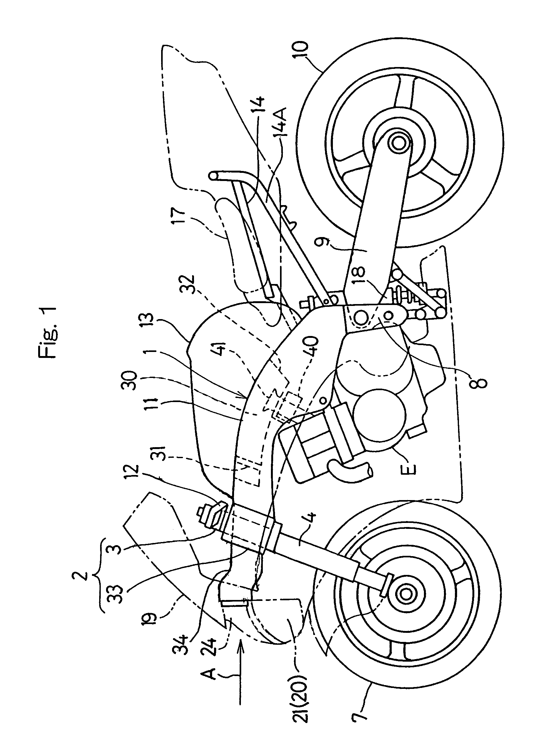
[0031]Reference will now be made to the accompanying drawings for the detailed description of a preferred embodiment of the present invention. Referring to FIG. 1 showing a schematic side view of a motorcycle equipped with an air intake system according to a preferred embodiment of the present invention, the motorcycle shown therein has a motorcycle frame structure 1 including a head tube 3 formed integrally with a head block 2 at a front end portion of the motorcycle frame structure 1. A front fork 4, which may be telescopic and which rotatably supports a front wheel 7 in a well known manner, is connected with the head tube 3 through a steering shaft (not shown) for rotation relative thereto so that the front wheel 7 can be turned leftwards or rightwards as a handlebar 12 is turned leftwards or rightwards.

[0032]On the other hand, the motorcycle frame structure 1 also includes swing arms 9 pivotally connected with swing arm brackets 8 positioned at a generally lower intermediate por...


PUM


Abstract

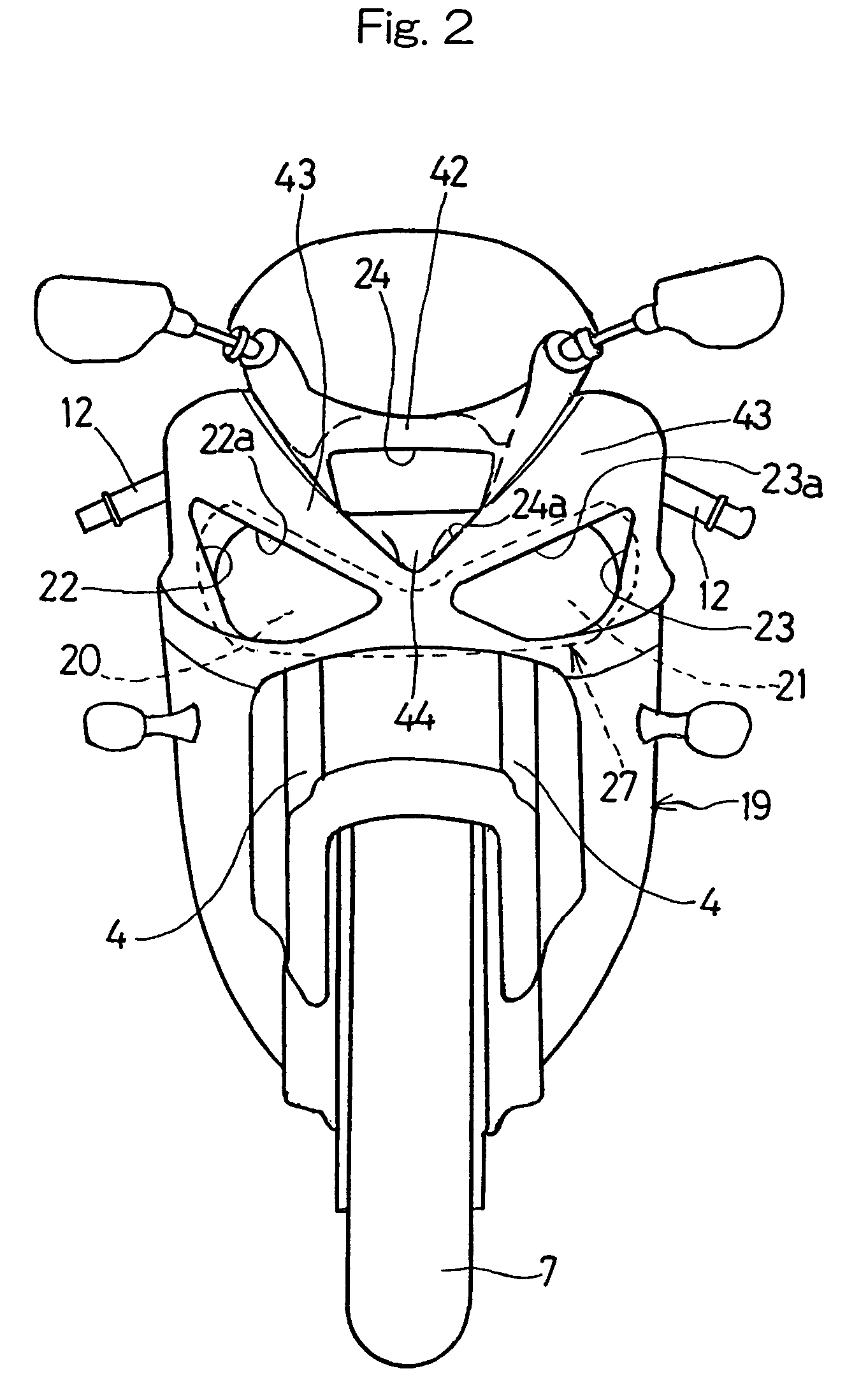
To provide an air intake system for a vehicle, so simple in structure as to reduce the cost and effective to increase the ram pressure, a front cowling (19) is mounted on a front portion of a vehicle body structure (1). This front cowling (19) has left and right headlight windows (20 and 21) aligned with left and right headlights (22 and 23), respectively, and also has an air intake opening (24) defined therein at a location above the headlight windows (20 and 21) for introducing an external combustion air (A) towards the vehicle engine (E). An intake air passage (35) is provided for introducing the combustion air (A), then entering the air intake opening (24), towards an air cleaner (30) by way of opposite lateral portions of a head tube (3).

Description

BACKGROUND OF THE INVENTION[0001]1. Field of the Invention[0002]The present invention generally relates to an air intake system for a vehicle combustion engine and, more particularly, to the air intake system for supplying a combustion air to the engine mounted on a motorcycle.[0003]2. Description of the Prior Art[0004]The air intake system hitherto employed in a motorcycle will be discussed with particular reference to FIGS. 8A to 8C. As shown in FIG. 8A, the motorcycle has a fairing or front cowling 51 having an air intake opening or air scoop 50 defined therein so as to open forwardly at a location substantially below a headlight 52 for introducing a combustion air A for use in a motorcycle internal combustion engine (not shown). The air scoop 50 is in communication with an air intake duct 55 which is in turn in communication with the motorcycle internal combustion engine in any known manner well known to those skilled in the art.[0005]According to the conventional air intake sys...

Claims


Application Information

Patent Timeline
Patent Type & Authority Patents(United States)
IPC IPC(8): B60K11/00B62J99/00B62J17/00F02B61/02F02M35/16
CPCF02B61/02F02M35/10013F02M35/10039F02M35/10098F02M35/10242F02M35/10262F02M35/112F02M35/162Y02T10/146Y02T10/12B62J40/10B62J17/10B62J17/02
Inventor IDEI, SHOJIFUKUMOTO, KEISHIFUKUUCHI, MASASHIFUKAMI, TAKASHI
Owner KAWASAKI MOTORS LTD
Learn More