
Helical fiber optic mode scrambler

a fiber optic mode and scrambler technology, applied in the direction of optical light guides, optical waveguide light guides, instruments, etc., can solve the problems of inconvenient design of remote laser delivery systems, art methods of introducing physical bends, and inconvenient design of laser delivery systems

Inactive Publication Date: 2007-09-11
CROWNOVER JOHN D
View PDF17 Cites 19 Cited by
  • Summary
  • Abstract
  • Description
  • Claims
  • Application Information

AI Technical Summary

Benefits of technology

"The present invention relates to an enhanced fiber optic mode scrambler that is suitable for remote laser delivery systems. The invention aims to maximize the energy transmission capacity and service life of the fiber optic cable by introducing physical bends in the fiber optic cable to fill more modes and reduce premature failure. The invention also addresses the issue of cladding modes in the fiber optic cable, which can cause premature failure. The invention provides more effective fiber optic mode scramblers that conserve physical space and improve energy capacity and life of the fiber optic cable. The invention may be used in communication systems, high-energy delivery systems, and other applications where light energy is transmitted through a fiber optic cable."

Problems solved by technology

It is common for the photons launched into a fiber optic cable to initially fill relatively few modes resulting in irregular photon density in the planes traverse to the direction the photons travel.
Prior art methods of introducing physical bends are problematic for fiber optic cables rated for high energy delivery due to the typically large cable diameter and corresponding increased resistant to mechanical bending.
However, design considerations involved in designing remote laser delivery systems differ substantially from fiber optic communication systems.

Method used


Image

  • Helical fiber optic mode scrambler
  • Helical fiber optic mode scrambler
  • Helical fiber optic mode scrambler

Examples


Embodiment Construction

[0012]The present invention may be employed to obtain one or more advantages such as increase the useful life of a fiber optic cable, increase the energy throughput of a fiber optic cable, implement smaller sized fiber optic scramblers, implement more efficient fiber optic scramblers and provide for robust implementations that are also easy to assemble.

[0013]In the following description, numerous specific details are set forth to provide a thorough understanding of the invention. However, it is understood that the invention may be practiced without these specific details. In other instances, structures and techniques have not been shown in detail in order not to obscure the invention.

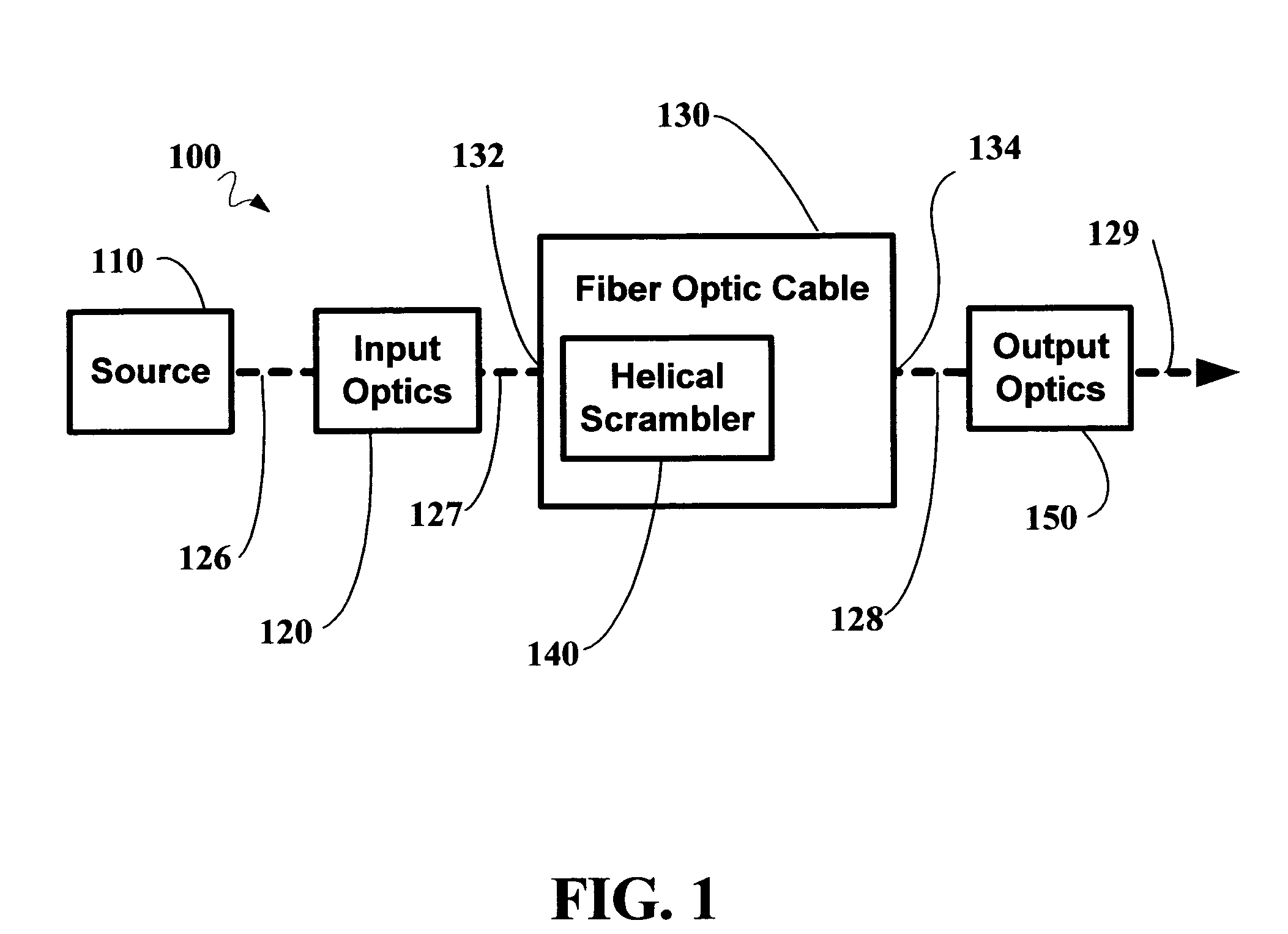
[0014]FIG. 1 is a block diagram of an exemplary remote laser delivery system 100 in accordance with the present invention. Remote laser delivery system 100 is suitable for a wide range of applications in which light energy is transmitted through a fiber optic cable 130 and directed to a target to provid...


PUM


Abstract

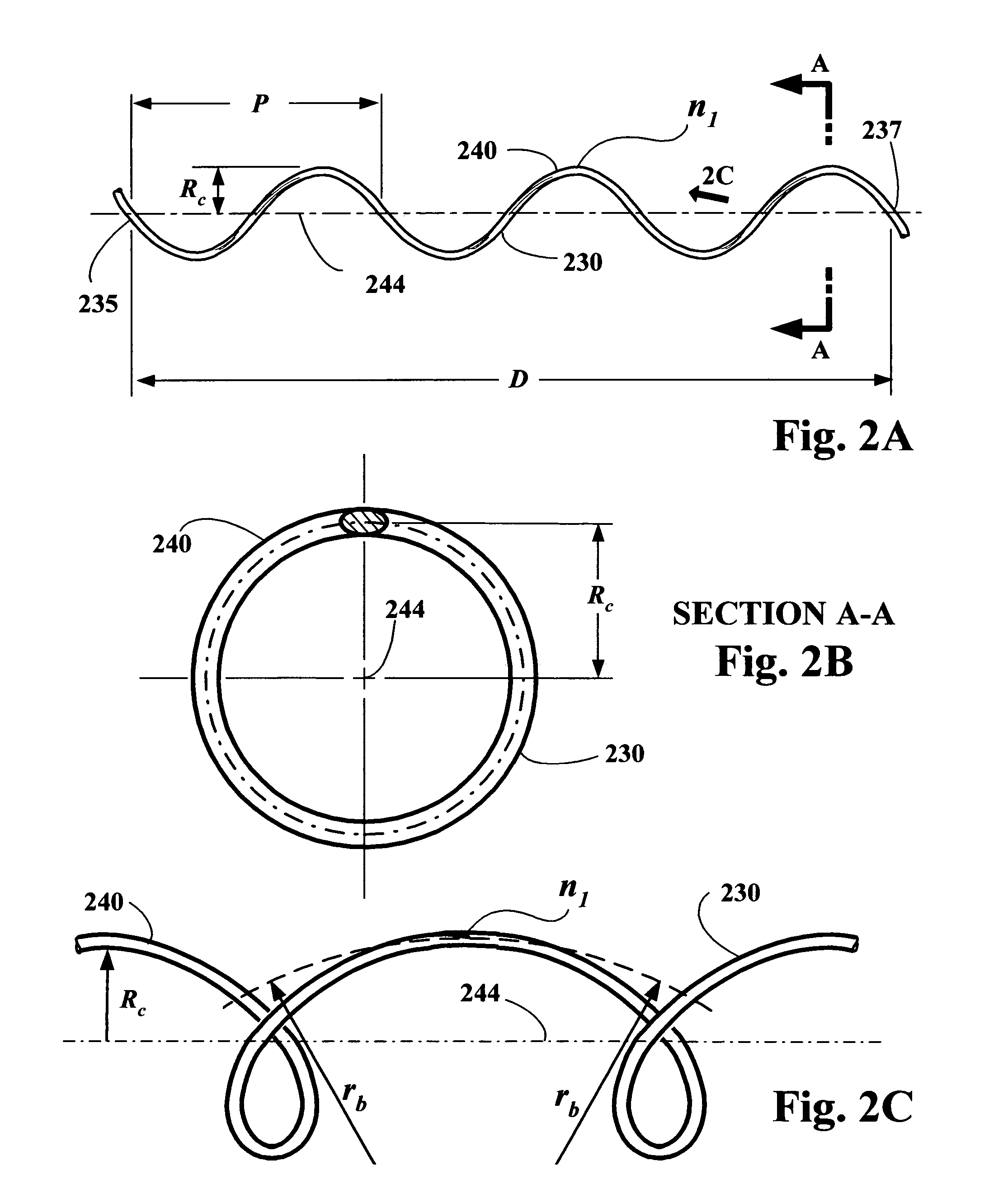
The methods and apparatus of the present invention provide advantages for remote laser delivery systems that conduct high levels of light energy through a fiber optic cable to a selectable target surface. Helical fiber optic mode scramblers in accordance with the present invention are an integral portion of a fiber optic cable having a rigid curvature predetermined to advantageously influence the intermodal dispersion characteristics of the fiber optic cable. The various aspects of the present inventions may be employed to increase the useful life of a fiber optic cable, increase the energy throughput of a fiber optics cable, implement smaller sized scramblers, implement more efficient scramblers or to provide for robust implementations that are also easy to assemble. Scrambler assemblies in accordance with the present invention include a support structure and a cylindrical sleeve that work in tandem to maintain to the predetermined spiral curvature of the helical mode scrambler.

Description

FIELD OF THE INVENTION[0001]The present invention relates to optical transmission systems; more particularity, the invention relates to an enhanced fiber optic mode scrambler, suitable for remote laser delivery systems.BACKGROUND OF THE INVENTION[0002]Remote laser delivery systems involve the delivery of light energy through a fiber optic cable and directing the light energy to a target surface to produce visual effects, heating or prolonged light exposure. UV photolithography, welding, engraving, sensors and analytical instruments are among the uses for remote laser delivery systems. In addition, the medical sciences have been advanced through the use of remote laser delivery systems to perform precise cutting and ablation of tissue in surgery, as well as, photodynamic non-ablative therapy such as hair removal, topical laser peel.[0003]Maximizing the energy transmission capacity and maximizing the service life of a fiber optic cable are important concerns in designing remote laser ...

Claims


Application Information

Patent Timeline
Patent Type & Authority Patents(United States)
IPC IPC(8): G02B6/00
CPCG02B6/14G02B2006/0209
Inventor CROWNOVER, JOHN D.
Owner CROWNOVER JOHN D
Learn More