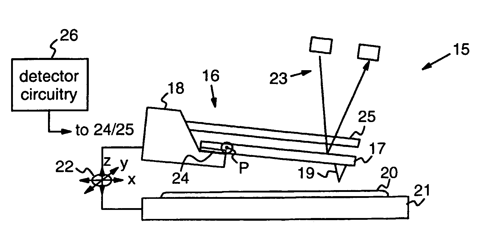
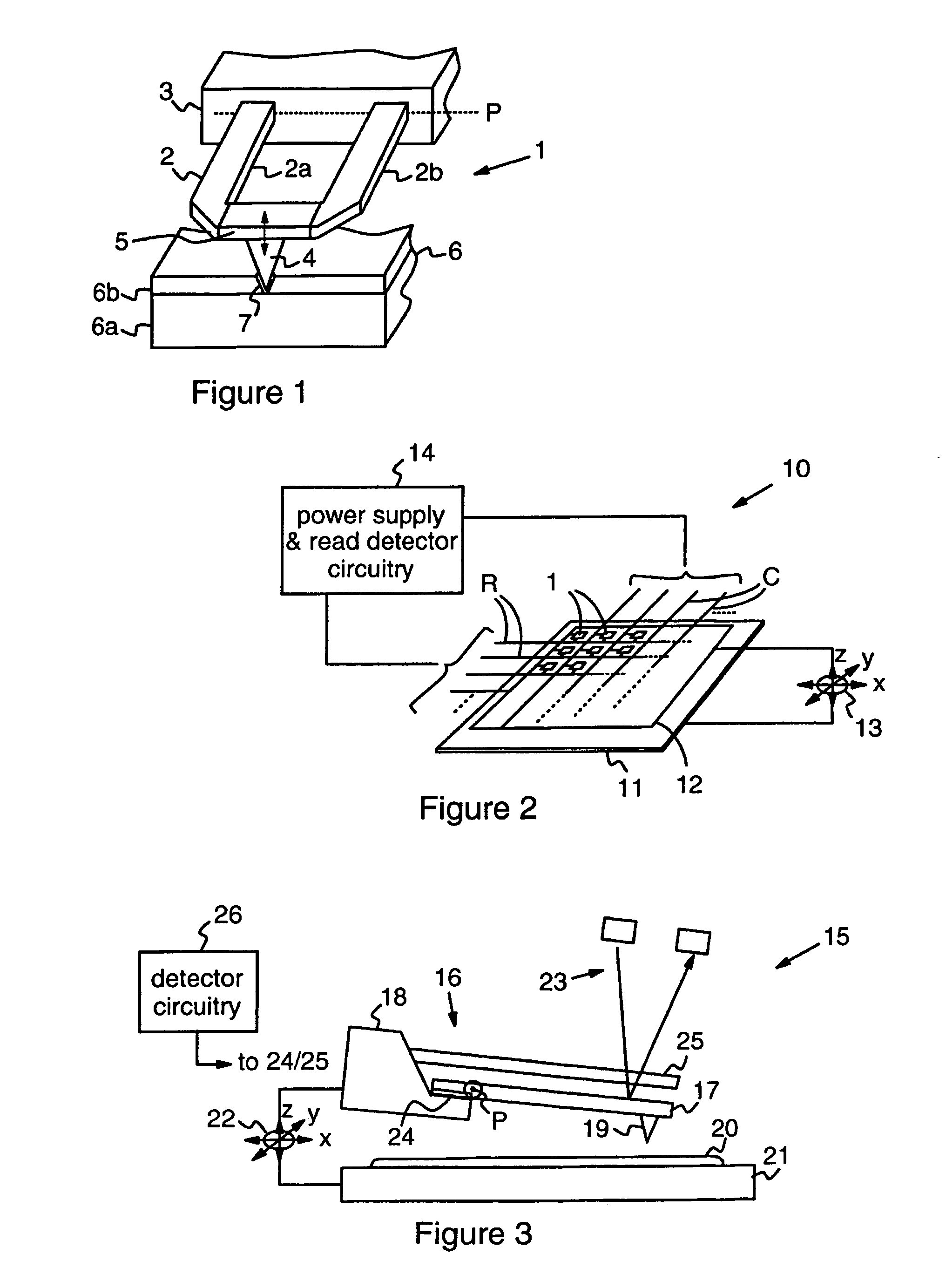
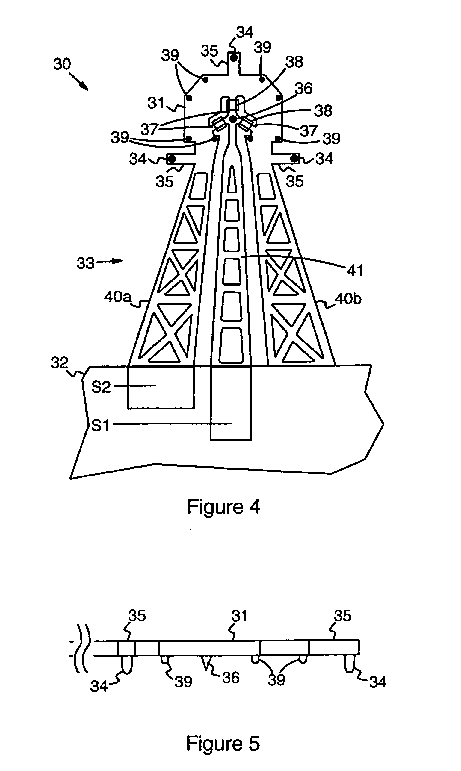
[0010]In embodiments of the present invention, therefore, the cantilever is formed by a tip platform which is connected to the support by a flexible arm arrangement, and two (at least) contact tips are provided on the tip platform. These contact tips provide points of contact with a surface to be scanned. As the platform is brought into engagement with the surface to be scanned, the arm arrangement flexes to allow the platform to orientate itself, bringing the contact tips into contact the scan surface. The platform is then at a well-defined orientation relative to the scan surface, and the scanning tip provided on the platform is appropriately positioned for the scanning operation. The design therefore provides a self-aligning cantilever device, significantly alleviating the difficulties of alignment presented by prior devices discussed above. Use of devices embodying the invention can render feedback mechanisms obsolete, and, where these mechanisms are employed, offers greater precision in the feedback operation.
[0011]In some embodiments of the invention there may be only two contact tips. This provides for self-orientation of the platform about an axis perpendicular to a line joining the two contact tips. While orientation about a
single axis may be sufficient for some applications, in others orientation about two orthogonal axes may be required. The tip platform in some embodiments may therefore have three non-aligned contact tips providing points of contact with the scan surface. Because the three contact tips are non-aligned, the free ends of these tips essentially define a plane relative to which the orientation of the platform is known. As the platform is brought into engagement with the scan surface, flexing of the arm arrangement allows the platform to orientate itself about two axes, bringing all three contact tips into contact the scan surface, whereupon the platform is then correctly aligned. While the use of only three contact tips here minimises wear on the scan surface, it may be appropriate to employ more than three contact tips in some embodiments. In these cases, the arrangement is such that the free ends of the contact tips lie substantially in the same plane since these tips provide the points of contact with the scan surface and thus determine the alignment of the platform in operation. The platform itself may comprise any convenient structure for carrying the tips, but ideally comprises a substantially planar structure, the orientation of the plane of the platform relative to the
contact plane defined by the free ends of the contact tips giving the required orientation of the platform relative to the scan surface in operation. Embodiments might be envisaged where it is desirable for the platform to be orientated at an angle to the scan surface in operation. However, in the preferred examples described below, the plane of the platform is substantially parallel to the
contact plane defined by the contact tips, whereby the platform is orientated substantially parallel to the scan surface in operation. This provides a simple, compact construction, and allows a well-defined force to be applied in applications where the platform is employed as an
electrode.
[0014]Where there are more than three contact tips one or more of which is a scanning tip mounted for independent movement as just described, the free ends of these tips lie substantially in the same plane within the limits of freedom of movement of the scanning tip(s). It will be appreciated that, in embodiments where, for example, a scanning tip is one of only three contact tips, then perpendicular movement of the scanning tip in operation can have some effect on the overall orientation of the platform. This may not be a concern in some embodiments, and may even be desirable, e.g. where it is precisely these changes in orientation which are detected to derive the scan output as in the tilting-platform arrangement suggested above. However, where it is desired to maintain platform orientation as constant as possible, then the spacing of the contact tips should be large compared to the extent of the perpendicular movement of the scanning tip, in particular so that platform movements resulting from the scanning tip movement are within acceptable
system limits, e.g. within
system noise levels. In general in embodiments of the invention, it will be desirable for the spacing of the contact tips to be large compared to the scanning tip size. Such a comparatively large contact tip spacing promotes good platform stability and improves effectiveness of the torque which brings a slightly misaligned cantilever into reliable alignment during engagement with the scan surface, as well as reducing the effect of scanning tip movement on desired platform orientation and / or scanning tip positioning as appropriate. Clearly, the relative dimensions here can be selected according to the parameters of a particular system, but in preferred embodiments the contact tip spacing is at least about ten times the height of the scanning tip, and more preferably about 100 times the scanning tip height.
[0016]It is the flexing of the arm arrangement which allows the orientation of the platform to bring the contact tips into contact with the scan surface, the flexible arrangement thus providing the necessary bending and / or twisting action. While an arrangement having a single flexible arm might be envisaged, particularly effective arrangements have a plurality of flexible arms extending between the platform and support. In such preferred embodiments, where the scanning tip is mounted for independent movement, for example via the flexible connecting portions mentioned above, the scanning tip may itself be connected to the support by a flexible arm of the arrangement to provide improved stability in operation. In any case, in particularly preferred embodiments the or each flexible arm comprises some form of lattice structure. That is, the arm comprises an
open framework such as a ladder or other
open structure with longitudinal elements interconnected by cross-pieces. Such a lattice structure is highly effective in providing the required flexibility for bending / twisting, with the added
advantage of strength in the longitudinal direction. This allows the movement necessary for self-alignment while preserving positional accuracy in the longitudinal direction.


