
Drive device for working vehicle and method of controlling the drive of working vehicle

a technology of working vehicles and drive devices, which is applied in mechanical equipment, braking systems, transportation and packaging, etc., can solve the problems of large gear change shock, and rapid deceleration of the vehicle, so as to reduce the speed of the vehicle, shorten the cycle time, and reduce the heat load

Active Publication Date: 2007-09-11
KOMATSU LTD
View PDF6 Cites 16 Cited by
  • Summary
  • Abstract
  • Description
  • Claims
  • Application Information

AI Technical Summary

Benefits of technology

[0016]The present invention was made in view of the above, its object being to provide a drive device for a working vehicle whereby a shortening of cycle time can be achieved and gear change shock during the forward / reverse running changeover action can be reduced while protecting the various clutch mechanisms in the transmission.
[0062]According to the first aspect of the present invention and the ninth aspect of the present invention, most of the kinetic energy of the vehicle is absorbed by the brake unit, reducing the vehicle speed with a smooth action and rapidly, and considerably decreasing the heat load to which the reverse clutch is subjected. Also, since the heat load to which the reverse clutch is subjected is considerably decreased, the need to perform the engagement action of the reverse clutch in a short time, as was necessary conventionally, when causing the vehicle to run in reverse after the speed reduction action, is eliminated. It is thereby possible to engage the reverse clutch gradually so that the operator does not feel a gear change shock.
[0063]With the present invention, a shortening of cycle time can be achieved and gear change shock during the forward / reverse running changeover action can be reduced while protecting the various clutch mechanisms in the transmission. the same effect can be obtained in the case of both the second aspect of the present invention and the tenth aspect of the present invention.
[0064]With the third aspect of the present invention and the fourth aspect of the present invention, generation of gear change shock when braking force is applied to the vehicle can be reliably prevented.
[0065]With the fifth aspect of the present invention, the engine rotational speed is temporarily reduced prior to commencement of the gradual engagement action of the reverse clutch, so gear change shock on commencement of the gradual engagement action of the reverse clutch can be further reduced. Also, since the engine rotational speed that had been temporarily decreased is increased after completion of the engagement action of the reverse clutch, the vehicle speed can be smoothly accelerated after the forward / reverse running changeover action. The same effect is obtained in the case of the sixth aspect of the present invention.
[0066]With the seventh and eighth aspect of the present invention, a lock-up clutch is disengaged during the forward / reverse running changeover action, so that the mechanical motive power of the engine is temporarily converted into dynamic energy of fluid in the torque converter before being again converted into mechanical motive power which is input to the transmission. In this way, gear change shock during the forward / reverse running changeover action is further reduced by the damping effect produced by the torque converter. Also, an improvement in the efficiency of transmission of motive power is achieved by direct input of the mechanical motive power of the engine to the transmission by putting the lock-up clutch in an engaged condition before and after the forward / reverse running changeover action. Thus it is arranged to perform the lock-up clutch engagement action in a gradual manner after the forward / reverse running changeover action, so there is no possibility of gear change shock being generated.

Problems solved by technology

Using an action of engaging the reverse clutch to decelerate the vehicle during forward running as in conventional drive devices is subject to the following problems.
This therefore gives rise to a gear change shock.
Consideration has been given to performing the action of engaging the reverse clutch for a short time, in order to suppress the heat load to which the reverse clutch is subjected, but, if this is done, rapid deceleration of the vehicle generates a large gear change shock.
Such an engagement action of course gives rise to gear change shock.
Problems similar to the above problems also arise in the case of changing over to forward running of the vehicle during reverse running.
Also, although, in the case of the drive device of Laid-open Japanese Patent Application Laid-open No. 6-272758, both the forward clutch and the reverse clutch are put in disengaged condition when changeover of the forward / reverse running is performed, so that there is no possibility of instantaneous drive force such as would advance the vehicle in the direction opposite to its current direction of running being applied from the transmission to the drive wheel, so a gear change shock as described under (A) cannot be produced, the speed stage changeover clutch is subjected to a large heat load during vehicle deceleration.
As a result, there is the problem that the life of the speed stage changeover clutch is decreased.

Method used


Image

  • Drive device for working vehicle and method of controlling the drive of working vehicle
  • Drive device for working vehicle and method of controlling the drive of working vehicle
  • Drive device for working vehicle and method of controlling the drive of working vehicle

Examples


Embodiment Construction

[0070]Specific embodiments of a drive device for a working vehicle according to the present invention are described below with reference to the drawings. These embodiments are examples of the application of the present invention to a working vehicle typified by a bulldozer.

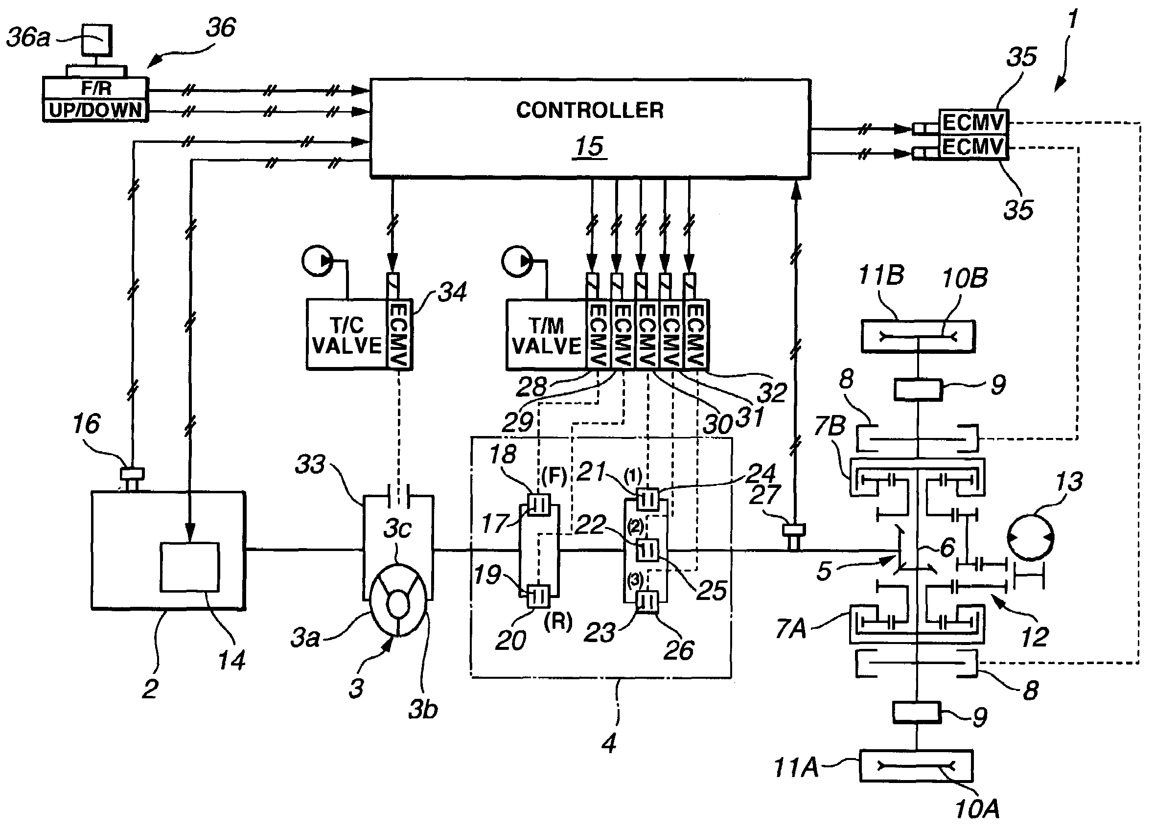
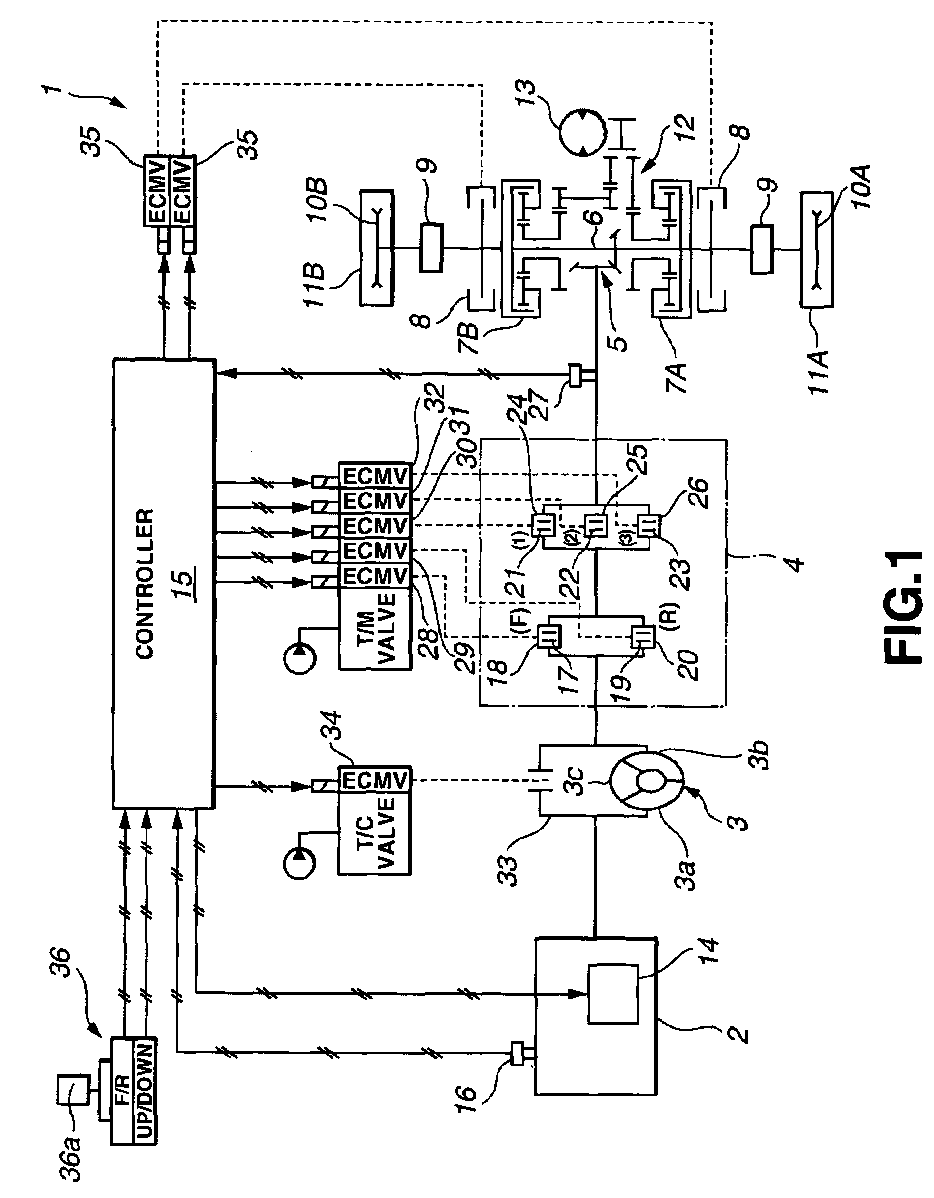
[0071]FIG. 1 is a diagrammatic view of the system layout of a bulldozer drive device according to an embodiment of the present invention.

[0072]In the drive device 1 shown in FIG. 1, rotational motive power from the engine 2 is transmitted to a torque converter 3, is transmitted from the output shaft of this torque converter 3 to a transmission 4, and is transmitted from the output shaft of this transmission 4 to a horizontal shaft 6 through a bevel gear 5.

[0073]Left and right planetary gear mechanisms 7A, 7B are respectively linked with the horizontal shaft 6.

[0074]An output shaft that is fixed to a planetary carrier of the left planetary gear wheel mechanism 7A is linked with a left sprocket wheel (left drive whe...


PUM


Abstract

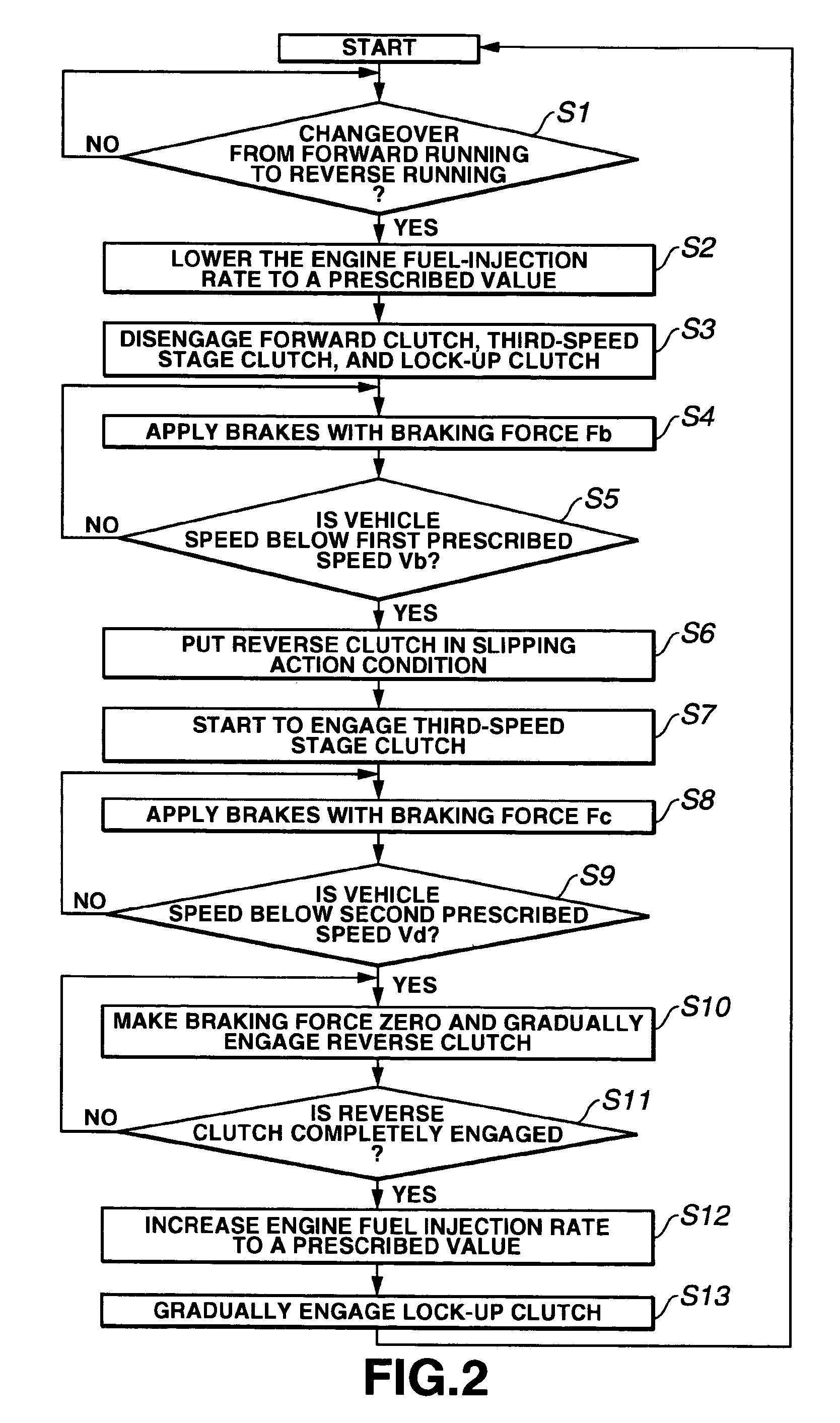
The present invention provides a drive device for a working vehicle whereby gear change shock during the forward / reverse running changeover action can be reduced while achieving shortening of cycle time and protecting various clutch mechanisms in the transmission. If a reverse running command is output from a running control device while the vehicle is running forward, an ECMV controls a braking force of a brake device so as to reduce a vehicle speed through a first prescribed speed to a second prescribed speed, and disengages the forward clutch. When the vehicle speed reaches the first prescribed speed, the ECMV puts the reverse clutch in a slipping action condition and, after the vehicle speed reaches the second prescribed speed, gradually engages the reverse clutch.

Description

BACKGROUND OF THE INVENTION[0001]1. Field of the Invention[0002]The present invention relates to a drive device suitable for mounting in a working vehicle such as for example a bulldozer and a drive method thereof[0003]2. Description of the Related Art[0004]A conventional drive device comprises an engine, transmission and drive wheel (sprocket wheel). The transmission comprises a forward running stage that is selected by engagement of a forward clutch, a reverse running stage that is selected by engagement of a reverse clutch and speed stages that are selected by a speed-stage changeover clutch.[0005]In this drive device, when the operator operates the running control device to output a forward running command, this forward running command causes the forward clutch to be engaged so that the motive power of the engine is transmitted to the drive wheels through the forward running stage and the currently selected speed stage of the transmission. As a result, the vehicle runs in the fo...

Claims


Application Information

Patent Timeline
Patent Type & Authority Patents(United States)
IPC IPC(8): B60W10/02B60W10/04B60W10/06B60W10/10B60W10/11B60W10/18B60W10/184F16H59/44F16H61/02F16H61/04F16H61/68F16H63/50
CPCB60W10/02B60W10/06B60W10/184B60W30/18045F16H61/0246B60W2710/0644Y10T477/6403Y10T477/745Y10T477/644Y10T477/753Y10T477/75Y10T477/6392
Inventor NAKAGAWA, TOMOHIROYAMAMOTO, SHIGERUOKA, SHUNJIOKADA, TOSHIKAZU
Owner KOMATSU LTD
Learn More