Fixing apparatus and an image formation apparatus
a technology of fixing apparatus and fixing member, which is applied in the direction of electrographic process apparatus, ohmic-resistance heating, instruments, etc., can solve the problems of uneven heat distribution of the fixing member in the width direction, difficult control of the temperature on both ends of the fixing member, and rapid rise of the temperature of the fixing apparatus
- Summary
- Abstract
- Description
- Claims
- Application Information
AI Technical Summary
Benefits of technology
Problems solved by technology
Method used
Image
Examples
embodiment 1
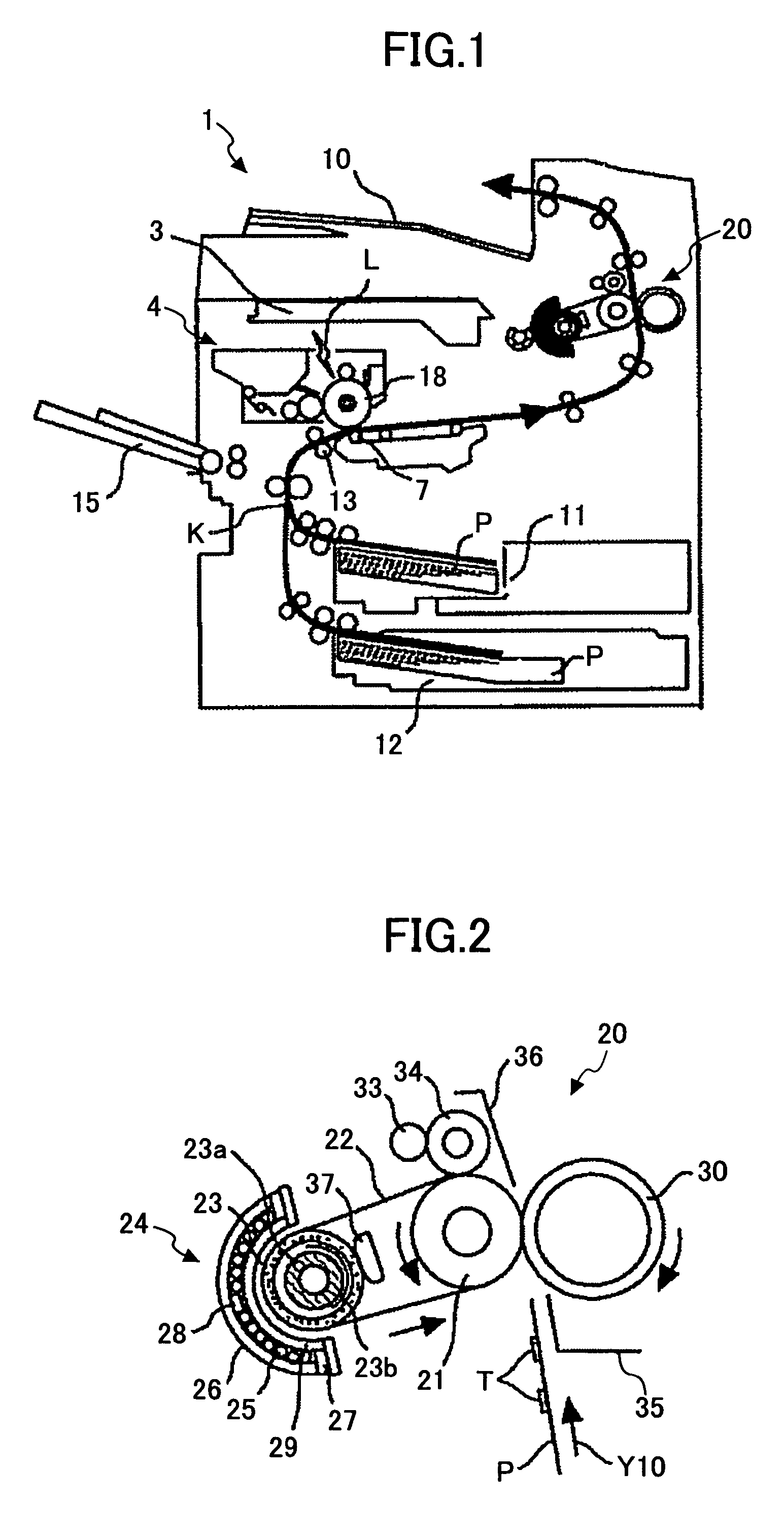
[0091]Embodiment 1 of the present invention is described in detail with reference to FIGS. 1 through 4.
[0092]First, the overall structure and operation of an image formation apparatus 1 according to Embodiment 1 are described.
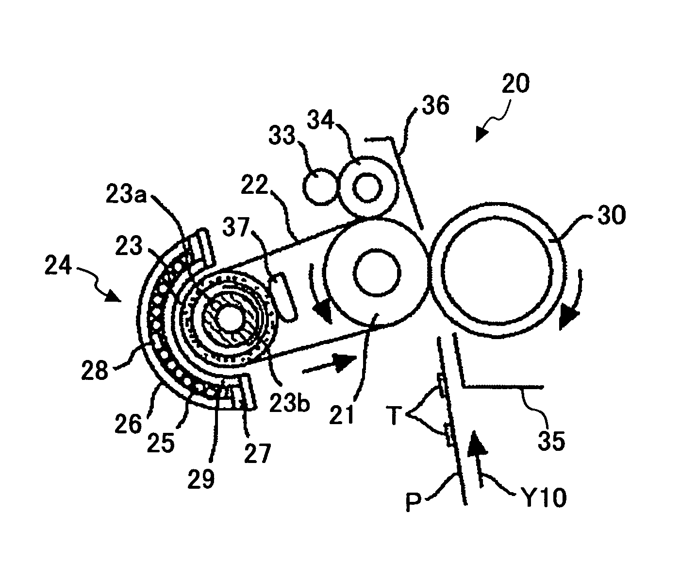
[0093]As shown in FIG. 1, the image formation apparatus 1 includes an exposure unit 3 that irradiates an exposure light L based on image information to a photo conductor drum 18, a process cartridge 4 that is detachably installed in the image formation apparatus 1, a transferring unit 7 that transfers a toner image formed on the photo conductor drum 18 to a recording medium P, a delivery tray 10 to which an output image is discharged, feed units 11 and 12 that store the recording media P, such as imprint paper, a resist roller 13 that conveys the recording medium P to the transferring unit 7, a manual feed unit 15 that feeds a recording medium P often having sizes different from the recording medium P stored by the feed units 11 and 12, and a fixing unit 20 tha...
embodiment 2
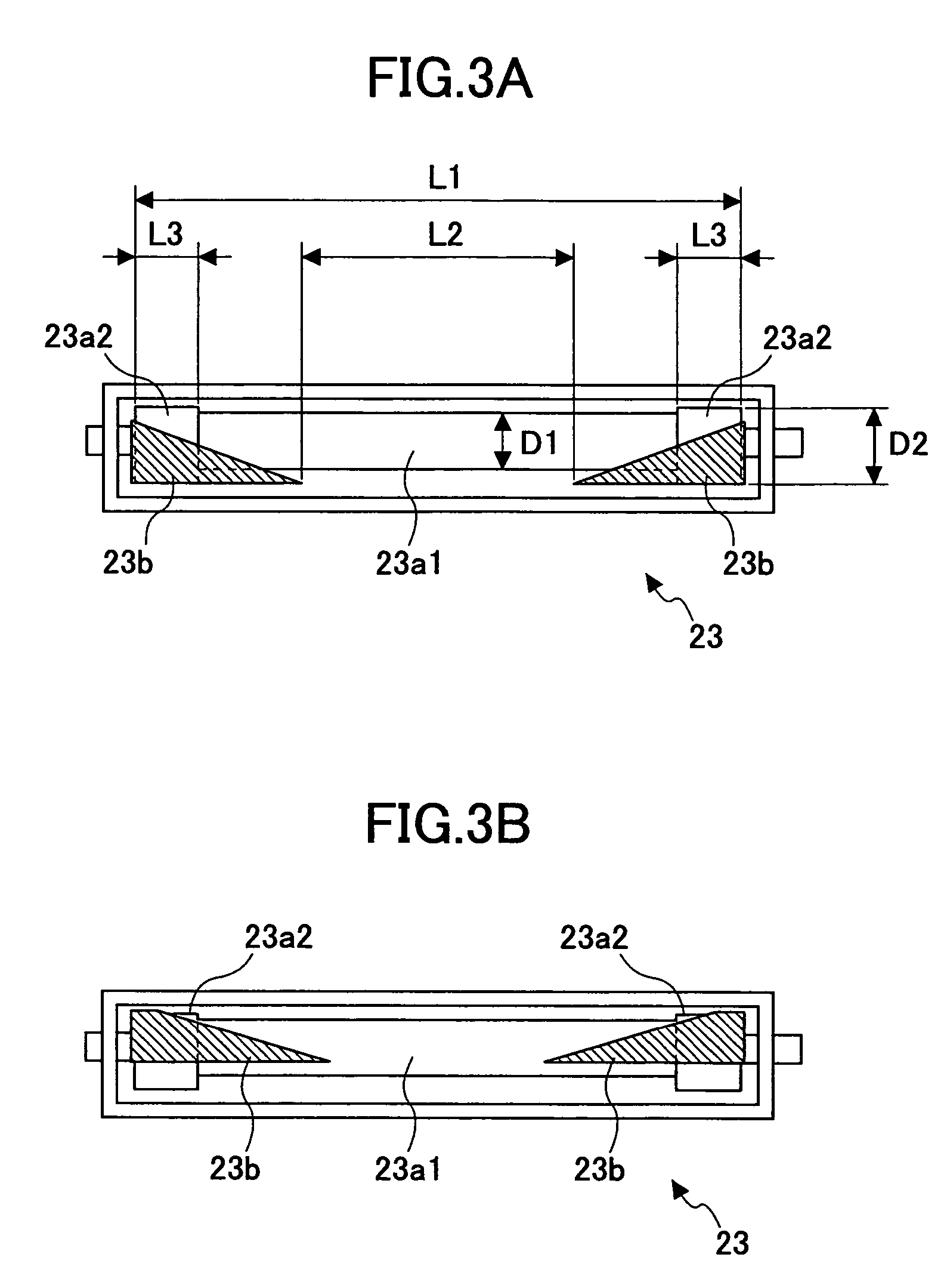
[0133]Embodiment 2 of the present invention is described in detail with reference to FIG. 5, which is a cross-sectional drawing showing the heating roller 23 installed in the fixing apparatus 20 according to Embodiment 2, and corresponds to FIG. 3A of Embodiment 1. As shown in FIG. 5, the shape of the internal core 23a (constituted by the small diameter section 23a1 and the large diameter sections 23a2), and the shape of the shielding members 23b are different from Embodiment 1.
[0134]The internal core 23a that is shaped like a solid cylinder having the large diameter sections 23a2, and the shielding members 23b are rotatably installed in the hollow cylinder of the heating roller 23 as shown in FIG. 5.
[0135]The large diameter sections 23a2 of the internal core 23a differ from those of Embodiment 1 in that the center axis of the large-diameter sections 23a2 is eccentric to (different from) the center axis of the small diameter section 23a1. The direction of the eccentricity is a direc...
embodiment 3
[0140]Embodiment 3 of the present invention is described in detail with reference to FIG. 6 that is a cross-sectional drawing showing the heating roller 23 installed in the fixing apparatus 20 according to Embodiment 3, and corresponds to FIG. 3A of Embodiment 1. The shape of the internal core 23a installed in the heating roller 23 of Embodiment 3 differs from Embodiment 1.
[0141]The hollow cylinder of the heating roller 23 includes the internal core 23a that is shaped like a solid cylinder having the large diameter sections 23a2, and the shielding members 23b that are rotatably installed as shown in FIG. 6.
[0142]The internal core 23a differs from Embodiment 1 in that taper sections 23a3, each having a width L4, are provided between each large diameter section 23a2 and the small diameter section 23a1.
[0143]The shielding members 23b are formed so that the shielded range wherein the internal core 23a is shielded can be increased from the edge of the internal core 23a, and decreased as ...
PUM
 Abstract
Description
Claims
Application Information
 - R&D
- Intellectual Property
- Life Sciences
- Materials
- Tech Scout
- Unparalleled Data Quality
- Higher Quality Content
- 60% Fewer Hallucinations
Browse by: Latest US Patents, China's latest patents, Technical Efficacy Thesaurus, Application Domain, Technology Topic, Popular Technical Reports.
© 2025 PatSnap. All rights reserved.Legal|Privacy policy|Modern Slavery Act Transparency Statement|Sitemap|About US| Contact US: help@patsnap.com


