
Trip coil drive circuit and electrical switching apparatus including the same

a technology of circuits and coil drives, applied in circuit-breaking switches, circuit-breaking switches for excess current, emergency protective devices, etc., can solve problems such as thermal breakdown of all connected equipment or adjacent equipment, open trip, and destructive to network protectors and corresponding feeder transformers, cables and related equipmen

Inactive Publication Date: 2007-09-04
EATON CORP
View PDF9 Cites 6 Cited by
  • Summary
  • Abstract
  • Description
  • Claims
  • Application Information

AI Technical Summary

Benefits of technology

The present invention provides a quadruple-redundant direct current source that can operate even if one of the storage capacitors fails. This is achieved by including three bulk storage capacitors, three corresponding fuse and diode isolation circuits, and an alternating current to direct current converter. The circuit monitoring the alternating current input and the first direct current output can isolate the failed capacitor and not affect the other capacitors or the operation of the entire circuit. The energy store may comprise a plurality of capacitors, and the first rectifier may include a first diode in series with a fuse and a second diode for each capacitor. The drive circuit includes an alternating current input, a first rectifier, an energy store, a circuit monitoring the alternating current input and the first direct current output, and a second rectifier responsive to the trip signal of the control relay to provide a third direct current output adapted to drive the trip coil.

Problems solved by technology

When either of the rectifier diode or the capacitor fails, the network protector fails to trip open.
The failure of the network protector to open, especially during a primary fault, can be destructive to the network protector and to the corresponding feeder transformer, cables and related equipment.
Such fault current typically runs in magnitudes of thousands of amperes, thereby causing thermal breakdown on all connected equipment or adjacent equipment due to excessive generated heat.
In turn, explosion and fire can cause destruction and excessive damage.

Method used


Image

  • Trip coil drive circuit and electrical switching apparatus including the same
  • Trip coil drive circuit and electrical switching apparatus including the same
  • Trip coil drive circuit and electrical switching apparatus including the same

Examples


example 1

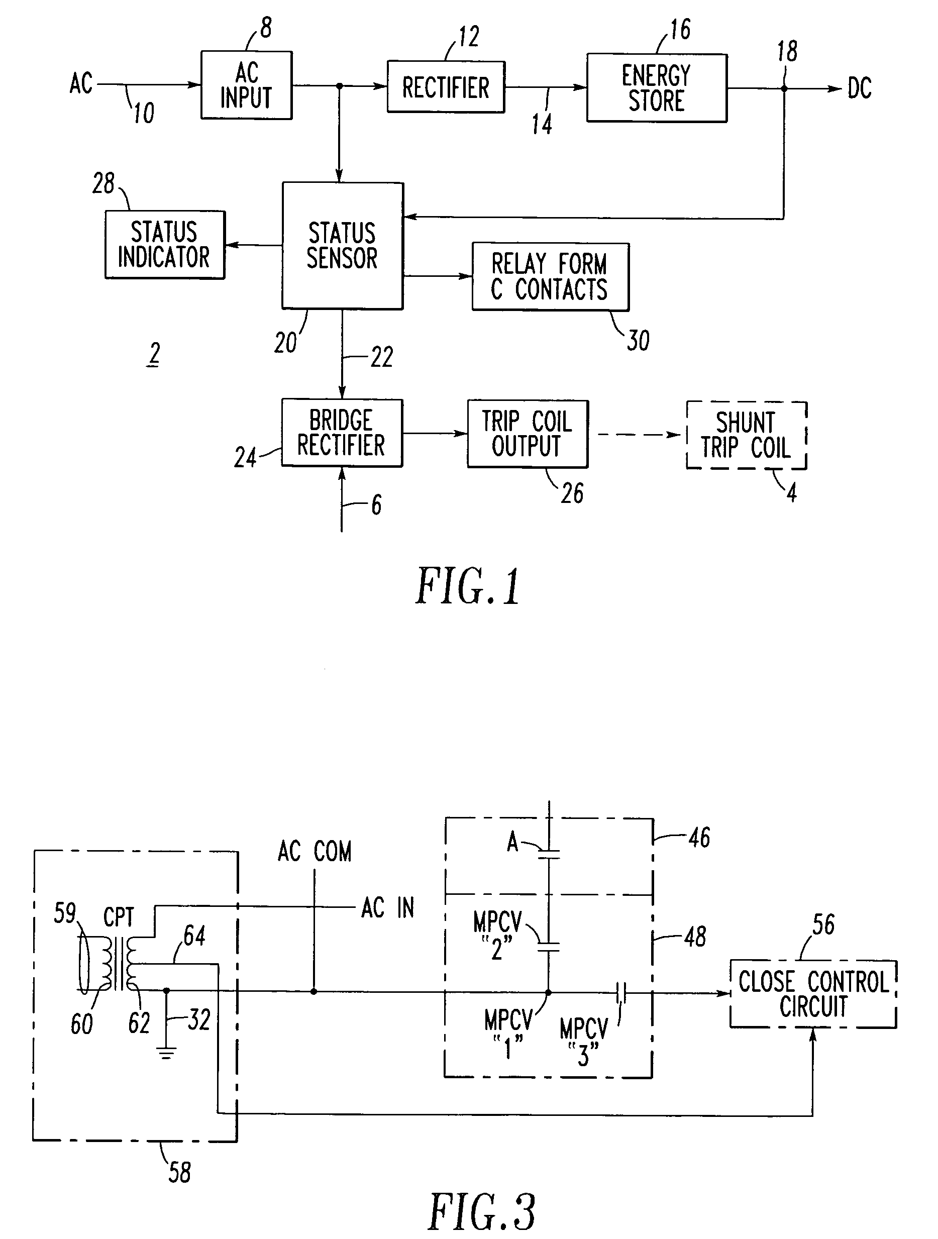
[0054]Preferably, the drive circuit 2 of FIG. 4 employs a NEMA 4X sealed enclosure (not shown) in order to prevent, for example, intrusion of liquid or gas contaminants. The enclosure may be submergible and waterproof to about, for example, a 15 foot depth.

example 2

[0055]The energy store 16 of the drive circuit 2 of FIG. 4 employs a triple-redundant backup direct current circuit and a self-isolating mechanism through the diodes 84-1,84-2,84-3 and the fuses 82-1,82-2,82-3 when any one or all of the capacitors 80-1,80-2,80-3, respectively, become defective.

example 3

[0056]The status sensor circuit 20 of the drive circuit 2 of FIG. 4 may provide built-in malfunction sensors 102,104 that provide remote notification via relay form C contacts 30 when the power components of the drive circuit 2 fail or when an external fault (e.g., loss of the alternating current voltage 10) occurs.


PUM


Abstract

A drive circuit, such as an electronic trip device, is for a shunt trip coil of a network protector. The drive circuit includes an alternating current input adapted to receive an alternating current voltage and a first half-wave rectifier adapted to provide a plurality of direct current voltages from the alternating current input. An energy store, such as a plurality of electrolytic capacitors, is adapted to provide a first direct current output from the direct current voltages of the first half-wave rectifier. A sensor circuit monitors the alternating current input and the first direct current output and provides a second output from one of the alternating current input and the first direct current output. A second full-wave rectifier responds to the second output and the trip signal to provide a third direct current output adapted to drive the network protector shunt trip coil.

Description

BACKGROUND OF THE INVENTION[0001]1. Field of the Invention[0002]This invention pertains generally to electrical switching apparatus and, more particularly, to network protectors. The invention also pertains to a trip coil drive circuit for a network protector.[0003]2. Background Information[0004]Electric power distribution networks, which supply power to a specified area such as, for example, a section of a city, an industrial complex or a large building, are fed at multiple points through feeders, each of which includes a network protector.[0005]A network protector is a circuit breaker adapted to trip and open the feeder upon detection of reverse power flow, that is, power flowing through the feeder out of the network rather than into the network. Typically, overcurrent protection is provided by other devices, such as fuses in series with the network protector.[0006]The network protector is energized by the voltage on the network at the point of connection of the network protector....

Claims


Application Information

Patent Timeline
Patent Type & Authority Patents(United States)
IPC IPC(8): H02H3/00H02H1/06H02H3/04H02H3/18
CPCH02H1/06H02H3/04H01H2083/203
Inventor ZIPAGAN, RONALD T.
Owner EATON CORP
Learn More