Electrical distribution wiring module

Inactive Publication Date: 2007-09-04
BAUM FAMILY TRUST DTD 1 11 2001 +143
View PDF29 Cites 47 Cited by
  • Summary
  • Abstract
  • Description
  • Claims
  • Application Information

AI Technical Summary

Benefits of technology

[0007]An electrical distribution wiring module benefits the electrical contractor in several respects. The wiring module is installed internally to an electrical box and associated functional modules are removably installed into the wiring module without exposure to or access to electrical system wiring attached behind the panel. The journeyman's work can complete at the rough phase, when installation of the wiring module is complete. Thus, there is no need for the journeyman to return to the job site during the makeup phase because any semi-skilled laborer can insert, for example, an appropriate outlet or switch module. Further, there is no wiring access after the rough phase, protecting wiring integrity. Also, there are no exposed conductors or parts inside the electrical box that can be inadvertently damaged during wall panel installation.
[0015]In an embodiment, cover mounts are generally centered proximate a top edge and proximate a bottom edge of the cover plate. Apertures are defined on the cover mounts for securing the cover plate to the wiring module box mounts. In a multi-gang box embodiment, a second cover plate is removably mounted to a second wiring module and disposed generally flush to the open face of a multi-gang electrical box. Portions of the cover plate and second cover plate overlap so as to prevent foreign material from entering the multi-gang box between the cover plates.

Problems solved by technology

Standard AC electrical systems are problematic in construction and use, with respect to costs, safety and functionality.
Also, during the makeup phase, installation of the wall panels can damage the work completed during the rough phase.
Another form of damage occurs when drywall compound or paint fouls the exposed cables, insulation and labeling.
From a general contractor's perspective, verification of the electrical contractor's work is not possible until after the makeup phase.
After the makeup phase, however, miswiring typically requires cutouts in the installed wall panels and associated patches after corrections are completed.
Further, the electrical system cannot be activated until after verification.
Thus, during the rough and makeup phases, electricity for tools and lighting must be supplied by generators, which create hazards due to fumes, fuel, and noise and are an unreliable electrical source.
In addition, until the trim phase is completed, unskilled personnel have access to the electrical cable.
Tampering can compromise the integrity of the electrical wiring and also create a safety problem after power is activated.
From a homeowner's perspective, there are problems with repair of the standard electrical wiring.
This exposure creates a shock hazard.
Further, a homeowner's reluctance to change out broken devices or to spend the money to hire an electrician also creates a shock and a fire hazard from continued use of cracked, broken or excessively worn outlets or switches.
In addition, the integrity of the original wiring becomes questionable if a homeowner or other third party removes and replaces an electrical device.
Miswiring by a third party can violate building codes and create shock and fire hazards, such as inadvertently switching the hot and neutral conductors, failing to attach ground wires, kinking or nicking conductors or improperly tightening connections.

Method used


Image

  • Electrical distribution wiring module
  • Electrical distribution wiring module
  • Electrical distribution wiring module

Examples


Embodiment Construction

System Overview

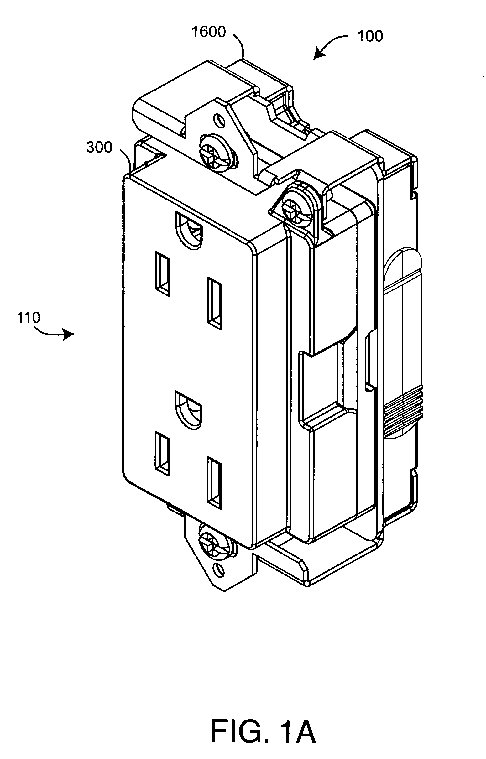
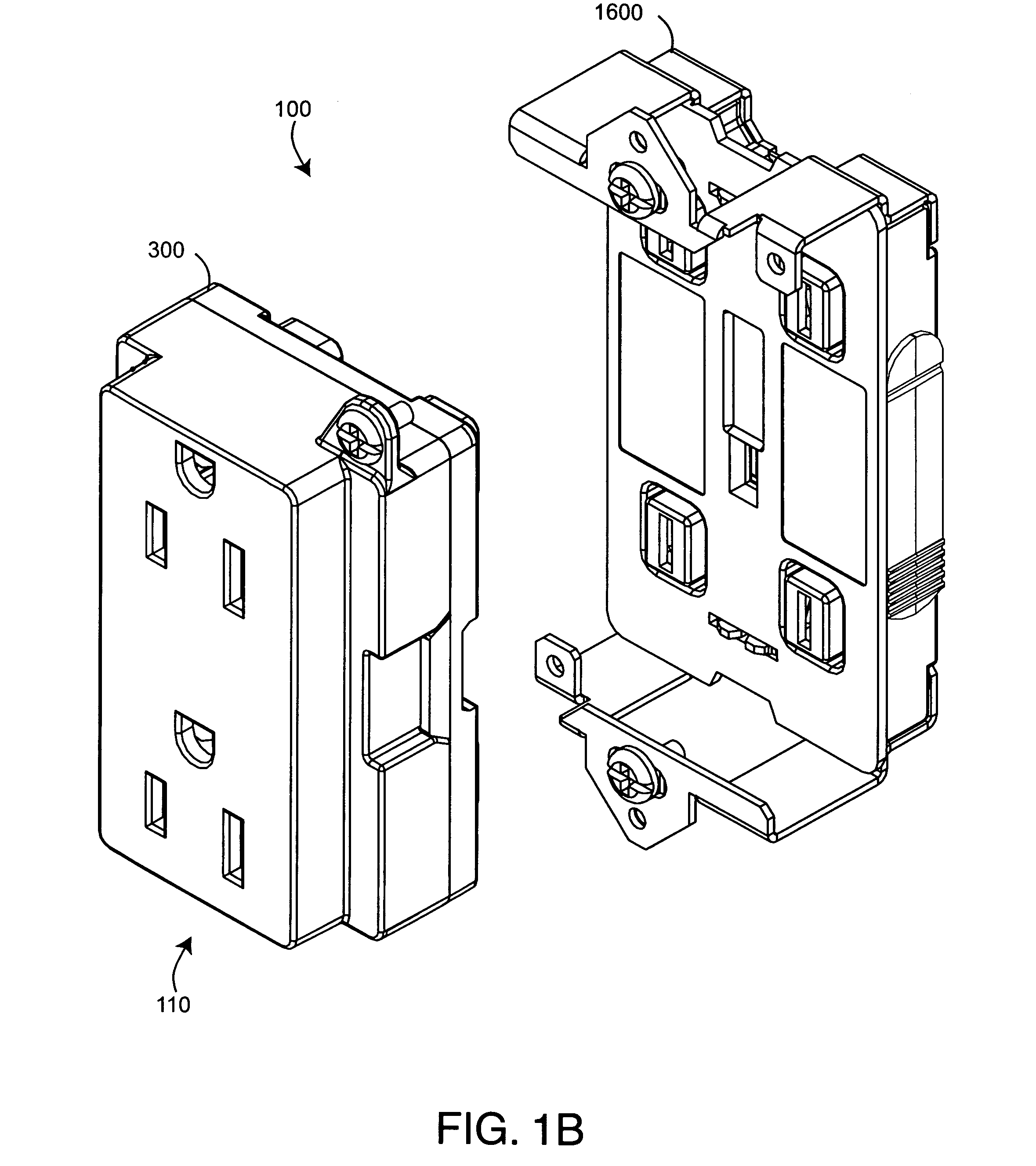
[0057]FIGS. 1–2 illustrate a safety module electrical distribution system 100 having a functional module 110 and a wiring module 1600. The electrical distribution system 100 is configured to mount within a standard electrical box (not shown), such as is typically installed within a building wall. In particular, the wiring module 1600 is configured to be easily installed within an electrical box, and a functional module 110 is configured to be removably plugged into the wiring module 1600, as described below. FIGS. 1A–B show an outlet module 300 in an installed and a removed position, respectively. FIGS. 2A–B show a switch module 900 in an installed and a removed position, respectively. A face plate (not shown) may be installed over a functional module 110 so as to provide an aesthetic trim.

[0058]As shown in FIGS. 1–2, each functional module 110 provides a user-accessible electrical distribution function. As shown in FIGS. 1A–B, the functional module 110 may be an outl...


PUM


Abstract

A wiring module is installed within an electrical box, wherein the wiring module is configured to connect to a power cable routed to the electrical box. The wiring module distributes electrical power according to a functional module that is pluggable into the wiring module. A cover is removably mounted to the wiring module so that the cover extends generally flush over an open face of the electrical box. The cover prevents plaster and other material from fouling the wiring module during wall panel installation and is removed after wall panel installation so as to plug the functional module into the wiring module.

Description

CROSS-REFERENCE TO RELATED APPLICATIONS[0001]The present application claims priority benefit under 35 U.S.C. § 120 to and is a continuation of U.S. patent application Ser. No. 11 / 110,351 entitled Electrical Distribution Wiring Module, filed Apr. 20, 2005 now U.S. Pat. No. 7,052,313, which claims priority benefit under 35 U.S.C. § 119(e) to U.S. Provisional Application No. 60 / 631,244 entitled Sealed Wiring Module, filed Nov. 26, 2004. U.S. patent application Ser. No. 11 / 110,351 is a divisional of U.S. application Ser. No. 10 / 443,444 entitled Safety Module Electrical Distribution System filed May 22, 2003 now U.S. Pat. No. 6,884,111, which claims priority benefit under 35 U.S.C. § 119(e) from U.S. Provisional Application No. 60 / 383,269 entitled Safety Plug-In Module Electrical Distribution System, filed May 23, 2002, and U.S. Provisional Application No. 60 / 441,852 entitled Safety Module Electrical Distribution System, filed Jan. 21, 2003. All of the aforementioned prior applications i...

Claims


Application Information

Patent Timeline
IPC IPC(8): H02G3/14
CPCH02G3/086H02G3/14
Inventor GORMAN, MICHAEL P.
Owner BAUM FAMILY TRUST DTD 1 11 2001
Why Eureka
Try Eureka