Enzymatic cascade bioreactor
a bioreactor and cascade technology, applied in bioreactors/fermenters for specific use, wort preparation, after-treatment of biomass, etc., can solve the problems of requiring a power source, and the limitation of biologically inspired fuel cells is the quantity and quality of fuel feedstock that can be provided
- Summary
- Abstract
- Description
- Claims
- Application Information
AI Technical Summary
Benefits of technology
Problems solved by technology
Method used
Image
Examples
example 1
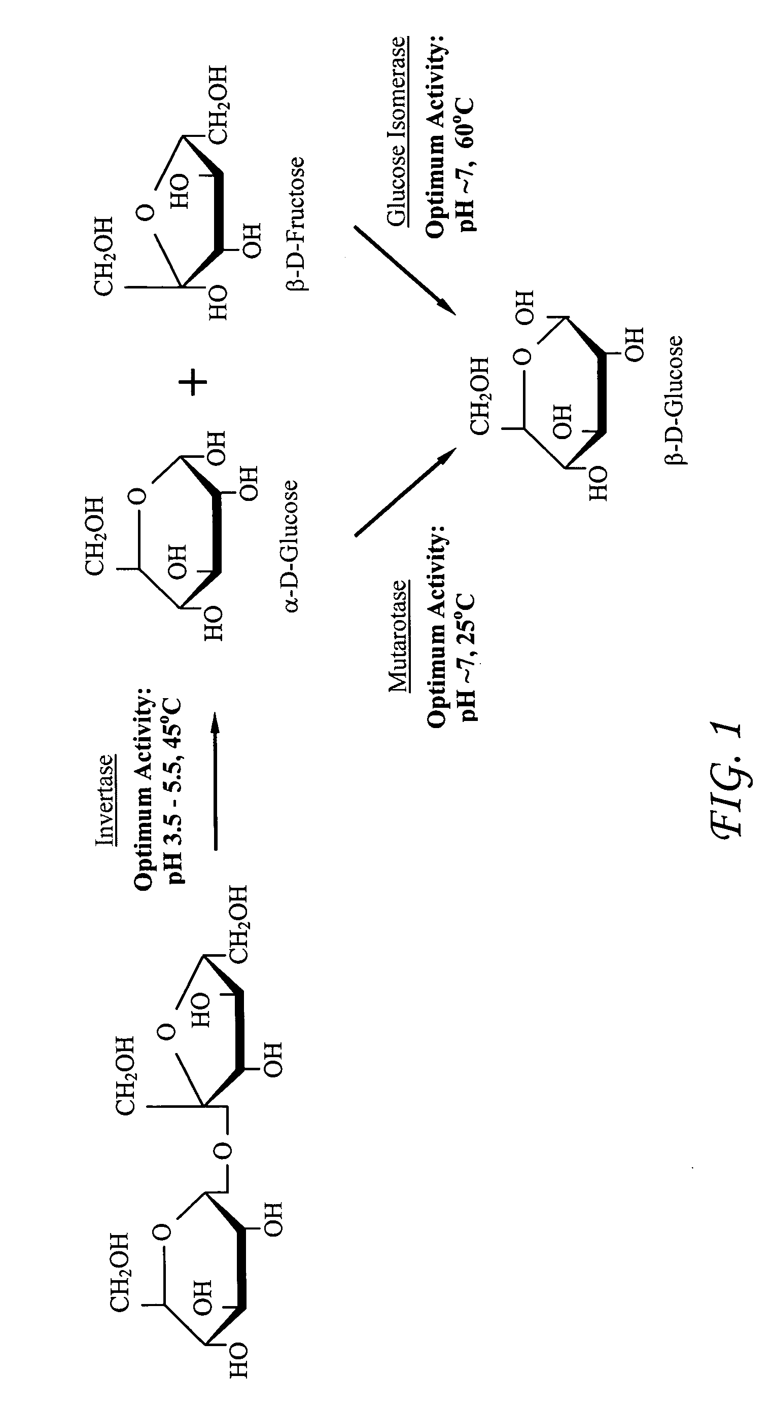
[0040]Although each enzyme has its own set of optimal pH and temperature conditions under which it performs best, we have obtained a 50% conversion of sucrose to glucose by placing three columns in series and providing a fuel stream with a pH=5.8 and 20mM MgCl2 at a temperature of 47° C. This pH and temperature is an average of the ranges that the individual enzymes prefer. Order of columns is invertase→glucose isomerase→mutarotase. Conditions were determined by averaging all three enzyme optimal operating conditions. The data obtained is presented in TABLE 3 below and shown graphically in FIG. 7.
[0041]
TABLE 3Measured Concentration of Sucrose, Glucose and Fructose in OutputStream of the Cascade Series of Columns of the Present Invention at apH = 5.8 and a temperature of 47° C.CollectionSucroseGlucoseFructoseTimeConcentrationConcentrationConcentration(sec)(mM)(mM)(mM)00.01.20.0150.01.50.0302.52.00.04576.1171.0163.06075.5178.0173.17581.8163.5164.69093.2157.4155.010592.4157.5153.712096...
example 2
[0042]We have obtained, however, a 77% sucrose to glucose conversion yield by placing three columns in series and providing a fuel stream that uses the optimum conditions for the invertase enzyme with a pH=4.6 at a temperature of 46° C. As before the order of the columns was invertase→glucose isomerase→mutarotase. The optimal operating conditions for the invertase enzyme were used. The data obtained is presented in TABLE 4 below and shown graphically in FIG. 8.
[0043]
TABLE 4Measured Concentration of Sucrose, Glucose and Fructose in OutputStream of the Cascade Series of Columns of the Present Invention at apH = 4.6 and a temperature of 46° C.CollectionSucroseGlucoseFructoseTimeConcentrationConcentrationConcentration(sec)(mM)(mM)(mM)00.00.10.4150.00.01.2300.025.019.64547.2185.4177.16021.0211.2182.77531.0211.1193.19051.9198.1177.410551.9196.6182.512045.1192.2175.6
example 3
[0044]We have obtained only a 2.7% conversion of sucrose to glucose by placing three columns in series and providing a fuel stream that uses the optimum conditions for the glucose isomerase enzyme with a pH=6.8 and 20 mM MgCl2 at a temperature of 62° C. The higher temperature needed for glucose isomerase optimum activity is detrimental to the invertase enzyme causing permanent inactivation and consequently a low conversion percentage. The data obtained is presented in TABLE 5 below and shown graphically in FIG. 9.
[0045]
TABLE 5Measured Concentration of Sucrose, Glucose and Fructose in OutputStream of the Cascade Series of Columns of the Present Invention at apH = 6.8 and a temperature of 62° C.CollectionSucroseGlucoseFructoseTimeConcentrationConcentrationConcentration(sec)(mM)(mM)(mM)02.80.00.7153.70.00.030145.61.53.245259.50.06.160280.42.23.375279.58.40.090285.25.50.0105295.14.10.0120279.67.50.0
[0046]Finally, while the invention has been described with respect to providing a source ...
PUM
 Abstract
Description
Claims
Application Information
 - R&D
- Intellectual Property
- Life Sciences
- Materials
- Tech Scout
- Unparalleled Data Quality
- Higher Quality Content
- 60% Fewer Hallucinations
Browse by: Latest US Patents, China's latest patents, Technical Efficacy Thesaurus, Application Domain, Technology Topic, Popular Technical Reports.
© 2025 PatSnap. All rights reserved.Legal|Privacy policy|Modern Slavery Act Transparency Statement|Sitemap|About US| Contact US: help@patsnap.com


