
Ultrasound radiation device into a material

a radiation device and ultrasound technology, applied in the direction of mechanical vibration separation, instruments, tomography, etc., can solve the problems of limited ultrasound-radiation angle of conventional transducers such as the idt for the leaky saw, and the difficulty of oblique incidence of ultrasound into liquids. , to achieve the effect of small size, light weight and convenient us

Inactive Publication Date: 2007-08-28
TODA KOHJI
View PDF4 Cites 3 Cited by
  • Summary
  • Abstract
  • Description
  • Claims
  • Application Information

AI Technical Summary

Benefits of technology

"The present invention provides an ultrasound radiation device that can change its driving frequency based on the depth of the material it is in. This allows for efficient operation under low power consumption and can radiate a message-signal, for example, music, into a cellular tissue. The device is easy to use, lightweight, and not affected by changes in circumstances, such as temperature. The invention also provides a piezoelectric substrate coated with a polymer film or made of a piezoelectric ceramic thin plate or made of a piezoelectric polymer thin film. The input- and output interdigital transducers have normal electrode-patterns or arch-shaped electrode-patterns. The invention also provides a method for generating an ultrasound radiation device using a piezoelectric substrate and a polymer film."

Problems solved by technology

However, such a conventional type of transducer has a difficulty in oblique incidence of the ultrasound into a liquid.
However, the leaky SAW traveling on a sufficiently thick substrate compared with the wavelength has only one mode without velocity dispersion.
Thus, a conventional transducer such as the IDT for the leaky SAW has a problem of a limited ultrasound-radiation angle.
However, these conventional devices have a difficulty in radiation of ultrasound beam reaching the bottom of a material with a high efficiency.
In addition, these conventional devices have a difficulty in continuous driving at a suitable frequency while moving itself on a surface of a material, of which the depth changes.

Method used


Image

  • Ultrasound radiation device into a material
  • Ultrasound radiation device into a material
  • Ultrasound radiation device into a material

Examples


first embodiment

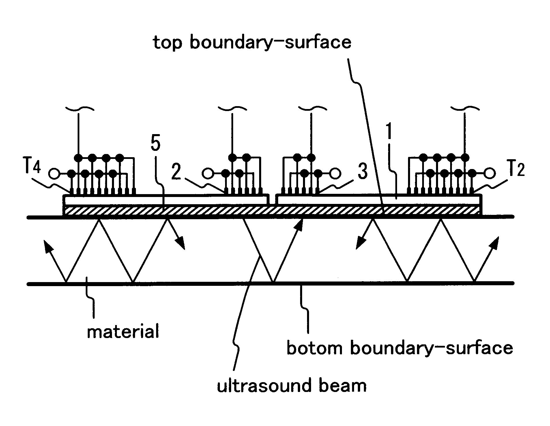
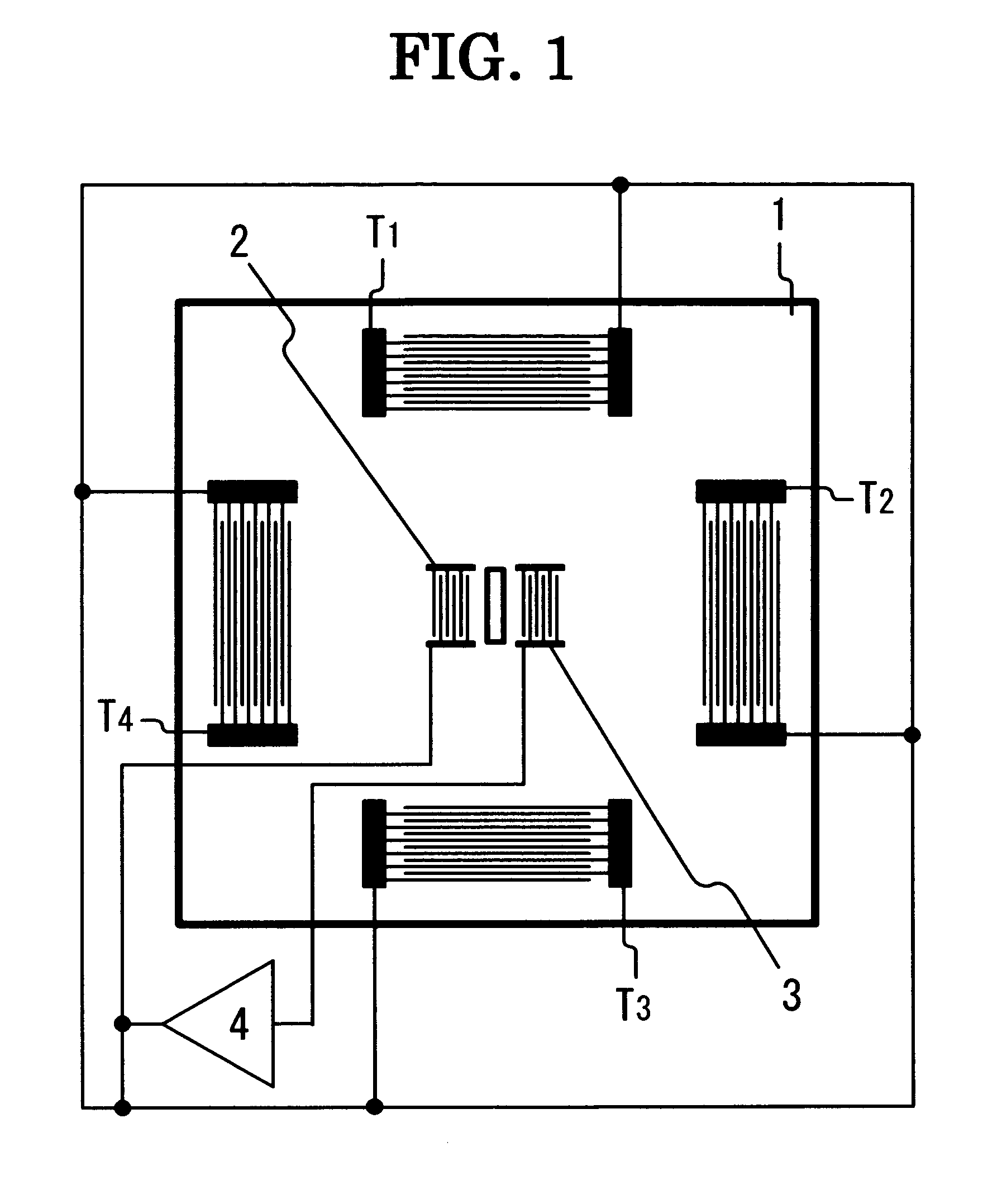
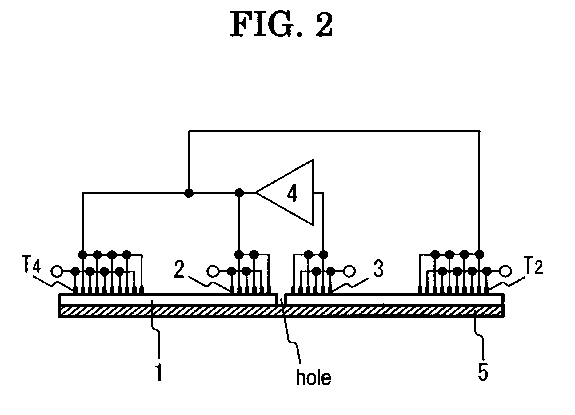
[0045]FIG. 1 shows a top plan view of an ultrasound radiation device into a material according to the present invention. The ultrasound radiation device into a material comprises piezoelectric substrate 1, input interdigital transducer 2, output interdigital transducer 3, four interdigital transducers (T1, T2, T3 and T4), amplifier 4, and polymer film 5 as silicone rubber, which is not drawn in FIG. 1. Though four interdigital transducers (T1, T2, T3 and T4) are used, only one interdigital transducer (T1, T2, T3 or T4) can be used in FIG. 1. Input interdigital transducer 2 and output interdigital transducer 3, having normal interdigital electrode-patterns made of aluminum thin films, respectively, are formed on a central surface-part of an upward surface of piezoelectric substrate 1. Interdigital transducers (T1, T2, T3 and T4) having normal interdigital electrode-patterns made of aluminum thin films, respectively, are formed on a surrounding surface-part of the upward surface of pi...

second embodiment

[0053]FIG. 6 shows a top plan view of an ultrasound radiation device into a material according to the present invention. The ultrasound radiation device into a material has the same construction as FIG. 1, except for the location of interdigital transducers (T1, T2, T3 and T4). The electrode-finger directions of interdigital transducers (T1, T2, T3 and T4) are oblique to those of input interdigital transducer 2 and output interdigital transducer 3. Interdigital transducers (T1, T2, T3 and T4) are mutually balanced for the center of the upward surface.

[0054]In the ultrasound radiation device into a material in FIG. 6, the radiation directions of the longitudinal waves from interdigital transducers (T1, T2, T3 and T4) are different from those of the longitudinal waves from input interdigital transducer 2 without exception. On the other hand, the radiation directions of the longitudinal waves from interdigital transducers (T1, T2, T3 and T4) are not always different from those of the l...

third embodiment

[0055]FIG. 7 shows a top plan view of an ultrasound radiation device into a material according to the present invention. The ultrasound radiation device into a material has the same construction as FIG. 1, except for the presence of modulator 6, the presence of input interdigital transducer 7 and output interdigital transducer 8 in place of input interdigital transducer 2 and output interdigital transducer 3, respectively, and the presence of four interdigital transducers (T5, T6, T7 and T8) in place of interdigital transducers (T1, T2, T3 and T4), respectively. Input interdigital transducer 7, output interdigital transducer 8, and interdigital transducers (Ts, T6, T7 and T8) have combination patterns, respectively, of which each is composed of a normal interdigital electrode-pattern and a dispersive electrode-pattern having interdigital periodicities of 285-380 μm. Input interdigital transducer 7 and output interdigital transducer 8 are arranged so that the end electrode-finger par...


PUM


Abstract

When input electric signals Ei (i=1, 2, . . . , n) with frequencies fi (i=1, 2, . . . , n), respectively, are applied to an input interdigital transducer, elastic waves are excited in a piezoelectric substrate. Leaky components of the elastic waves are radiated into a material in the form of longitudinal waves, which are reflected at a bottom boundary-surface of the material. One of reflected longitudinal waves are detected at an output interdigital transducer as a delayed output signal with one of the frequencies fi. When the delayed output signal is applied to at least one interdigital transducer for radiation, an elastic wave is excited in the piezoelectric substrate. A leaky component of the elastic wave is radiated into the material in the form of a longitudinal wave, which is reflected at the bottom boundary-surface and re-reflected at a top boundary-surface of the material, and thus a continuous reflection occurs.

Description

BACKGROUND OF THE INVENTION[0001]The present invention relates to a device for radiating an ultrasound into a material by means of using an assembly composed of a piezoelectric substrate, input- and output interdigital transducers for delay-line oscillation, and another at least one interdigital transducer for ultrasound radiation into a material.[0002]Popularly, a thickness mode piezoelectric transducer, of which operation frequency is dependent on the thickness of a piezoelectric substrate, is used for emitting an acoustic wave. However, such a conventional type of transducer has a difficulty in oblique incidence of the ultrasound into a liquid.[0003]When the piezoelectric substrate is in contact with a liquid, an interdigital transducer (IDT) on the piezoelectric substrate is useful. By use of the IDT on the piezoelectric substrate, sufficiently thicker compared with the wavelength of a surface acoustic wave (SAW) thereon, the SAW propagates in the form of a leaky wave that is mo...

Claims


Application Information

Patent Timeline
Patent Type & Authority Patents(United States)
IPC IPC(8): H03H9/25
CPCG01N29/07G01N29/2462H03H9/14555H03H9/14561H03H9/14564H03H9/6486G01N2291/0421H03H9/14547
Inventor TODA, KOHJI
Owner TODA KOHJI
Learn More