
Performance operator control apparatus

a technology of operator control and control apparatus, which is applied in the direction of instruments, electrophonic musical instruments, measurement devices, etc., can solve the problems of unnecessarily increasing the total affecting the overall area of the circuit board, and affecting the overall number of lines adapted to the keyboard

Active Publication Date: 2007-08-21
YAMAHA CORP
View PDF8 Cites 2 Cited by
  • Summary
  • Abstract
  • Description
  • Claims
  • Application Information

AI Technical Summary

Benefits of technology

The invention provides a performance operator control apparatus that allows a player piano to effectively use monitoring signals from key motions without increasing the size of the circuit board or the number of lines. The apparatus includes an operator I / O control unit with multiple ports for input and output, and a control unit circuit for performing calculations to produce drive data for the performance operator. The operator I / O control unit sends the physical parameters from sensors attached to the performance operators to the control unit circuit, which uses the same control routine for the performance operators. The apparatus also includes a plurality of drive components for driving the performance operators and an electrification abnormality detector for detecting abnormality in the drive components. The apparatus allows for multidimensional servo controls on one or multiple performance operators and simplifies the software by collecting monitoring signals during execution of servo controls.

Problems solved by technology

This unnecessarily increases the overall area of a circuit board and the total number of lines adapted to a keyboard.
Similar problems may occur due to the necessity of the ‘specifically designed’ control circuit.
This problem occurs not only in the solenoid abnormality detection circuit detecting the abnormality but in the other circuitry using the configuration for detecting internal monitoring signals, for example, in the circuitry for detecting the temperature of a circuit board of a keyboard so as to output a temperature detection signal to a control circuit and the like.
This may require specific lines for transmitting signals representing the abnormality, which in turn unnecessarily increases the overall area of a circuit board and the number of lines adapted to a keyboard.
Similar problems may occur due to the necessity of the ‘specifically designed’ control circuit.
This also requires specific lines for transmitting signals representing the sensor output, which in turn unnecessarily increases the overall area of a circuit board and the number of lines adapted to the keyboard.
That is, the aforementioned modification adapted to the conventional technology causes complication in circuit configurations, which in turn increases the probability that an error may occur in a certain part of the circuitry, whereby it becomes very difficult to precisely notify users of the occurrence of the abnormality.

Method used


Image

  • Performance operator control apparatus
  • Performance operator control apparatus
  • Performance operator control apparatus

Examples


first embodiment

1. First Embodiment

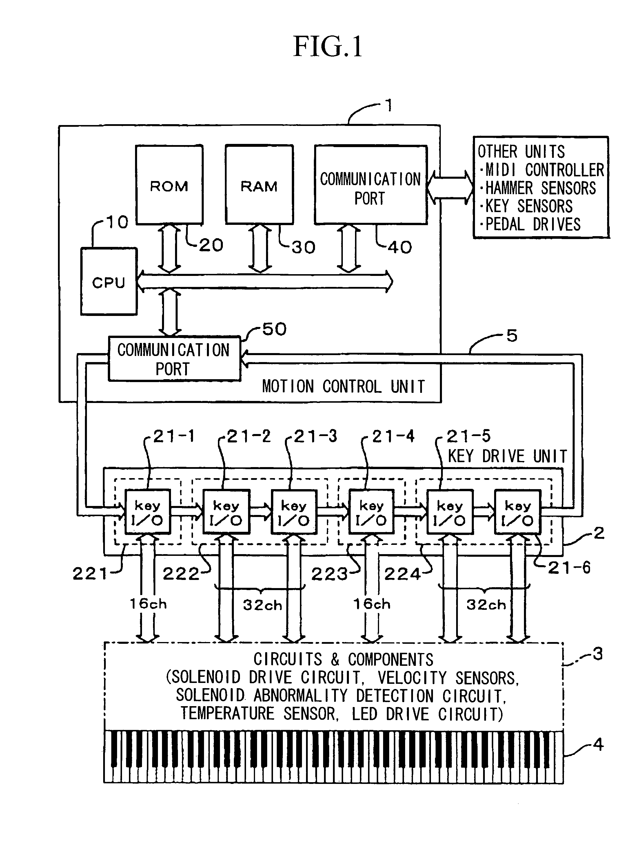
[0031]FIG. 1 is a block diagram showing essential parts of a player piano adopting a performance operator control apparatus in accordance with a first embodiment of the invention. The player piano of FIG. 1 is equipped with a keyboard 4 having eighty-eight keys (including white keys and black keys), which correspond to performance operators in this invention. A motion control unit 1, which serves as a control unit circuit and is basically configured by a digital signal processor (i.e., DSP), comprises a CPU 10, a ROM 20, a RAM 30, a first communication port 40, and a second communication port 50. The CPU 10 executes programs stored in the ROM 20 so as to perform drive controls on the respective keys of the keyboard 4 in an automatic performance mode (or an auto-play mode). The first communication port 40 performs data input / output operations on other circuits and units, wherein it receives performance data, namely, MIDI data (based on the “Musical Instrument Digit...

second embodiment

2. Second Embodiment

[0059]Next, a player piano incorporating a performance operator control apparatus in accordance with a second embodiment of the invention will be described with reference to FIGS. 4 to 6, wherein parts and steps identical to those shown in FIGS. 1 to 3 are designated by the same reference numerals. The overall constitution of the player piano shown in FIG. 4 is basically identical to the overall constitution of the player piano shown in FIG. 4 except for the internal configuration and channel assignment of the key drive unit 2, which comprises the key I / O control ICs 21-1 to 21-6.

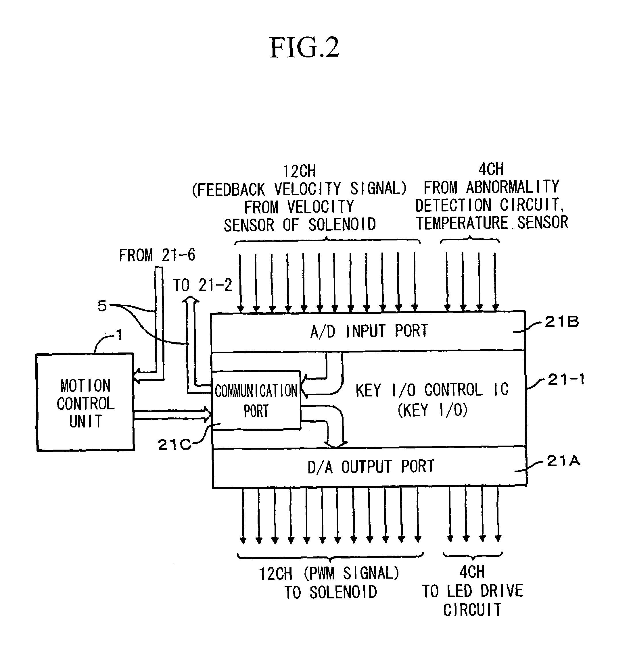
[0060]FIG. 5 shows the key I / O control IC 21-1 whose hardware configuration is basically similar to that of the key I / O control IC 21-1 shown in FIG. 2, wherein the 16-channel D / A output port 21A converts digital data (i.e., 16 bits per channel) serially input thereto into analog signals, which are output therefrom in parallel, and the 16-channel A / D input port 21B converts analog signal...


PUM


Abstract

A performance operator control apparatus adapted to a player piano comprises a motion control unit and a key drive unit comprising a plurality of key I / O control ICs in connection with keys of a keyboard, which are driven by solenoids so as to realize automatic performance, wherein upon detection of electrification abnormality of solenoids or temperature abnormality, LEDs are turned on to indicate the abnormality. The key I / O control ICs receive velocity signals regarding the solenoids so as to perform feedback controls on the keys in the automatic performance. In addition, unoccupied channels of the key I / O control ICs, which are not assigned to the keys and sensors, are used to input monitoring signals and to output inspection signals. Herein, the abnormality is determined based on the difference between pre-inspection data and post-inspection data, which are transferred using a loop connection channel of the key I / O control IC.

Description

BACKGROUND OF THE INVENTION[0001]1. Field of the Invention[0002]This invention relates to performance operator control apparatuses for controlling various types of apparatuses equipped with performance operators, such as keyboard instruments (e.g., player pianos), which allow users to generate acoustic sounds by depressing keys for striking strings, which allow users to record musical tone data such as MIDI (i.e., Musical Instrument Digital Interface) data, and which are capable of playing automatic performance using acoustic sounds by driving keys based on musical tone data, and multidimensional performance control apparatuses (e.g., music playing devices and game playing devices), which are equipped with performance operators for performing drive controls on musical performance and which are equipped with other types of operators such as joysticks for performing drive controls on musical performance in a multidimensional manner.[0003]This application claims priority on Japanese Pa...

Claims


Application Information

Patent Timeline
Patent Type & Authority Patents(United States)
IPC IPC(8): G10H1/32G01H3/00G10F1/02G10H1/00
CPCG10F1/02G10H1/0058G10H2240/056
Inventor OBA, YASUHIKOFUJIWARA, YUJIURA, TOMOYUKIKATO, TADAHARU
Owner YAMAHA CORP
Learn More