
Pull-out display shelf

Inactive Publication Date: 2007-08-21
TRION IND
View PDF18 Cites 52 Cited by
  • Summary
  • Abstract
  • Description
  • Claims
  • Application Information

AI Technical Summary

Benefits of technology

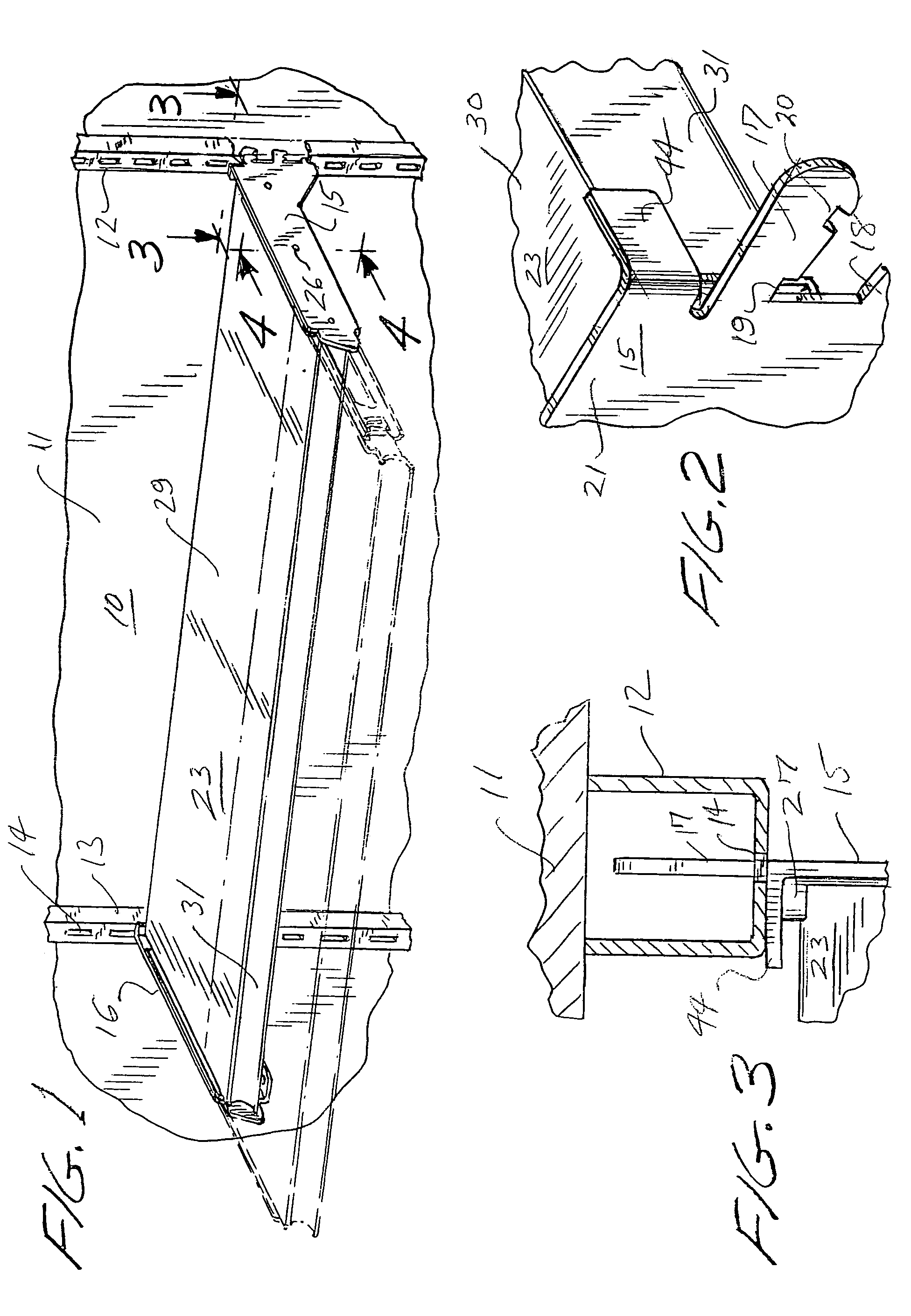
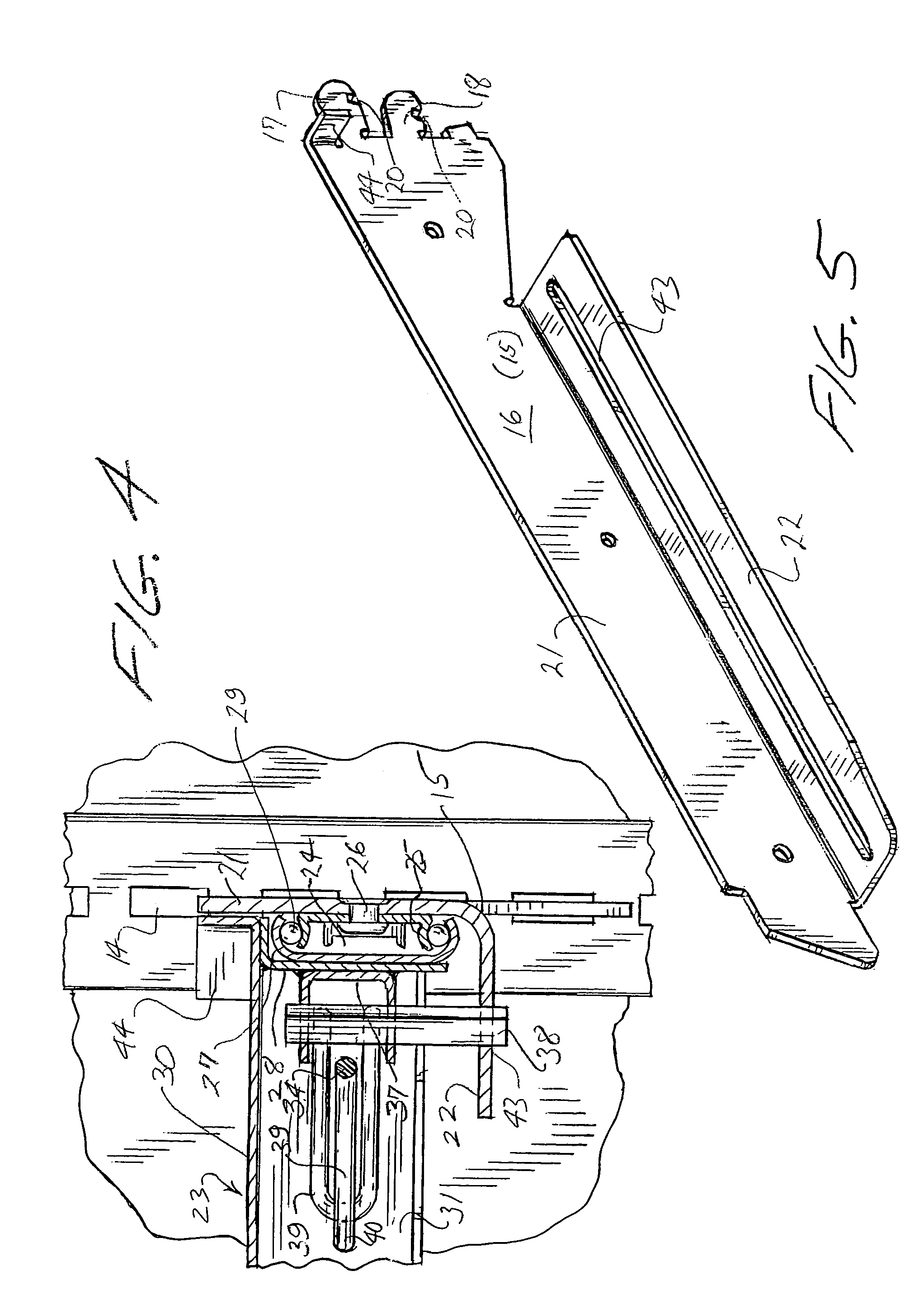
[0004]Pursuant to the present invention, a pull-out shelf mechanism is provided in which the side supports for a movable shelving system are both significantly strengthened and simplified in structure, so as to achieve improved performance while at the same time reducing the cost of manufacturing the unit. In the prior art structure referred to, the side supports, in order to accommodate the necessary position locking arrangement, are of rather complex construction, involving several independent components requiring separate manufacturing, handling and assembly. In the structure of the invention, by contrast, the side supports are constructed of a rugged, one-piece metal shape, which both significantly strengthens the side support elements and simultaneously accommodates the locking mechanism without additional components. To this end, the side support elements are formed of a relatively heavy sheet metal material, shaped in a generally L-shaped cross section and thus having significant rigidity. The L-shaped configuration, comprising a vertical side wall and a horizontal bottom wall joined integrally and in one piece therewith, enables an elongated locking slot to be formed within the bottom panel, eliminating the need for extra parts to be constructed and installed as in the prior art mechanism.

Problems solved by technology

In the prior art structure referred to, the side supports, in order to accommodate the necessary position locking arrangement, are of rather complex construction, involving several independent components requiring separate manufacturing, handling and assembly.
When the shelf is unlocked, however, to accommodate forward or rearward movement, the mechanism can be somewhat laterally unstable, which can be exacerbated in some cases when the shelf is stocked with heavy merchandise and / or pulled out to an extended position.

Method used


Image

  • Pull-out display shelf
  • Pull-out display shelf
  • Pull-out display shelf

Examples


Embodiment Construction

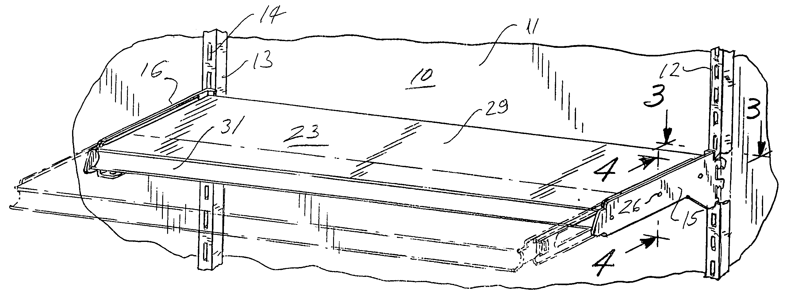
[0012]Referring now to the drawings, the reference numeral 10 designates a typical gondola structure used in many point-of-purchase displays and typically including a base structure (not shown), a back wall 11 and spaced uprights 12, 13. The uprights 12, 13 typically may be spaced on four foot centers, and are formed with a plurality of vertical disposed slotted openings 14 for mounting shelf side supports 15, 16. These supports are formed with notched mounting tabs 17, 18, one above the other, which are adapted to be inserted into vertically adjacent pairs of the slotted openings 14. Notches 19 engage the uprights 12, 13 at the lower ends of the slotted openings 14, to lock the side supports in assembled relation to the vertical uprights. Typically, the mounting tabs are provided with secondary notches 20, which enable the shelf assembly to be mounted with a downward slant, which is useful in the display of certain types of merchandise.

[0013]Pursuant to the invention, the side supp...


PUM


Abstract

A pull-out display shelf assembly having spaced-apart support structures mounted on gondola uprights, for example, and supporting a display shelf for movement between fully retracted and extended positions, with locking means for securing the shelf structure in any set position. The locking mechanism includes vertically rotatable square locking bars freely movable in a locking track when aligned therewith, and having locking engagement with the track when rotated out of alignment with the track. Simplified and improved support structures are formed of heavy gauge sheet metal, bent into an L-shaped configuration for strength and rigidity and formed to provide elongated locking slots in horizontal bottom panels of the L-shaped supports. Component parts are minimized and rigidity and locking action are improved. Stabilizing tabs at the inner ends of the support brackets minimize lateral flexing of the brackets when the shelf is released for movement relative to the support brackets.

Description

BACKGROUND OF THE INVENTION[0001]The display of merchandise in mass merchandising outlets and the like typically involves extensive shelving installations. Typical forms of display shelving comprise gondola structures forming support stands for the shelving. The gondolas may comprise a base from which extends a back wall panel including .two or more vertical uprights formed with slots or other openings to receive shelving at various levels. Stores frequently try to position shelves with relatively minimal vertical clearance between the contents of one shelf and the position of the shelf next above, in order to maximize the number of shelves, and therefore the amount of merchandise displayed, in a given gondola. However, as vertical shelf spacing becomes more compressed, it becomes more difficult to stock and service individual shelves, particularly lower shelves, because of the difficulty and inconvenience in reaching the back areas of the shelves.[0002]To facilitate access to back ...

Claims


Application Information

Patent Timeline
IPC IPC(8): E04G3/20
CPCA47B96/025A47F5/0093
Inventor NAGEL, THOMAS O.
Owner TRION IND
Learn More