Eureka AIR delivers breakthrough ideas for toughest innovation challenges, trusted by R&D personnel around the world.

Embroidery frame transfer device and attachment

a transfer device and embroidery frame technology, applied in the field of embroidery frame transfer devices, can solve the problems of inability to interchange embroidery frames, inability to use embroidery frames of the old kind accustomed by users,

Inactive Publication Date: 2007-08-21
BROTHER KOGYO KK
View PDF20 Cites 16 Cited by
  • Summary
  • Abstract
  • Description
  • Claims
  • Application Information

AI Technical Summary

Problems solved by technology

Thus, the embroidery frame transfer devices of different mounting structures of the embroidery frames have no interchangeability between the embroidery frames.
In case the user changed the embroidery frame transfer device so that the embroidery frame mounting structure of the embroidery frame transfer device of the new kind purchased is different from that of the embroidery frame transfer device of the old kind owned, therefore, there arises a disadvantage that the embroidery frame for the old kind accustomed by the user cannot be used in the embroidery frame transfer device of the new kind.

Method used


Image

  • Embroidery frame transfer device and attachment
  • Embroidery frame transfer device and attachment
  • Embroidery frame transfer device and attachment

Examples


Embodiment Construction

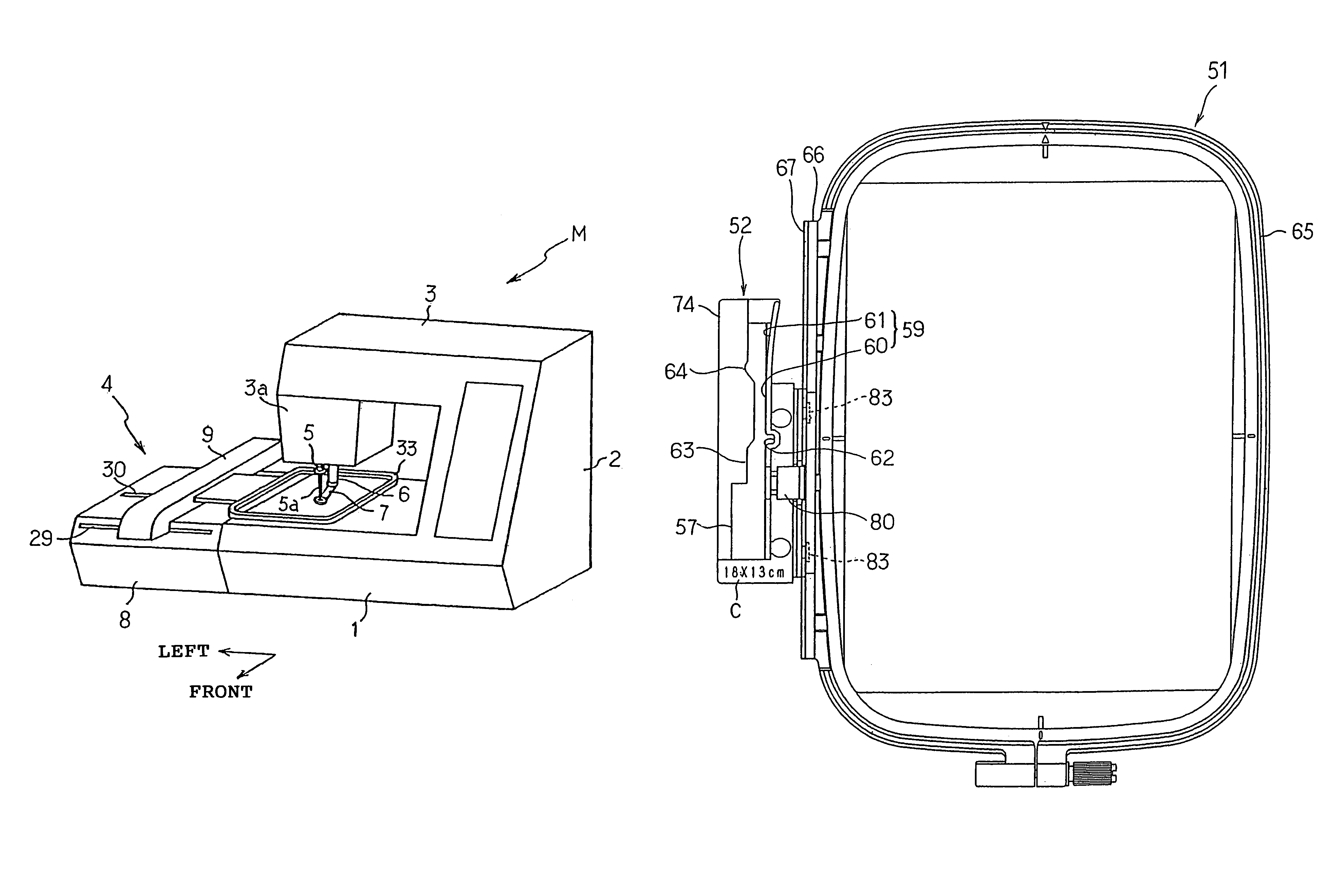
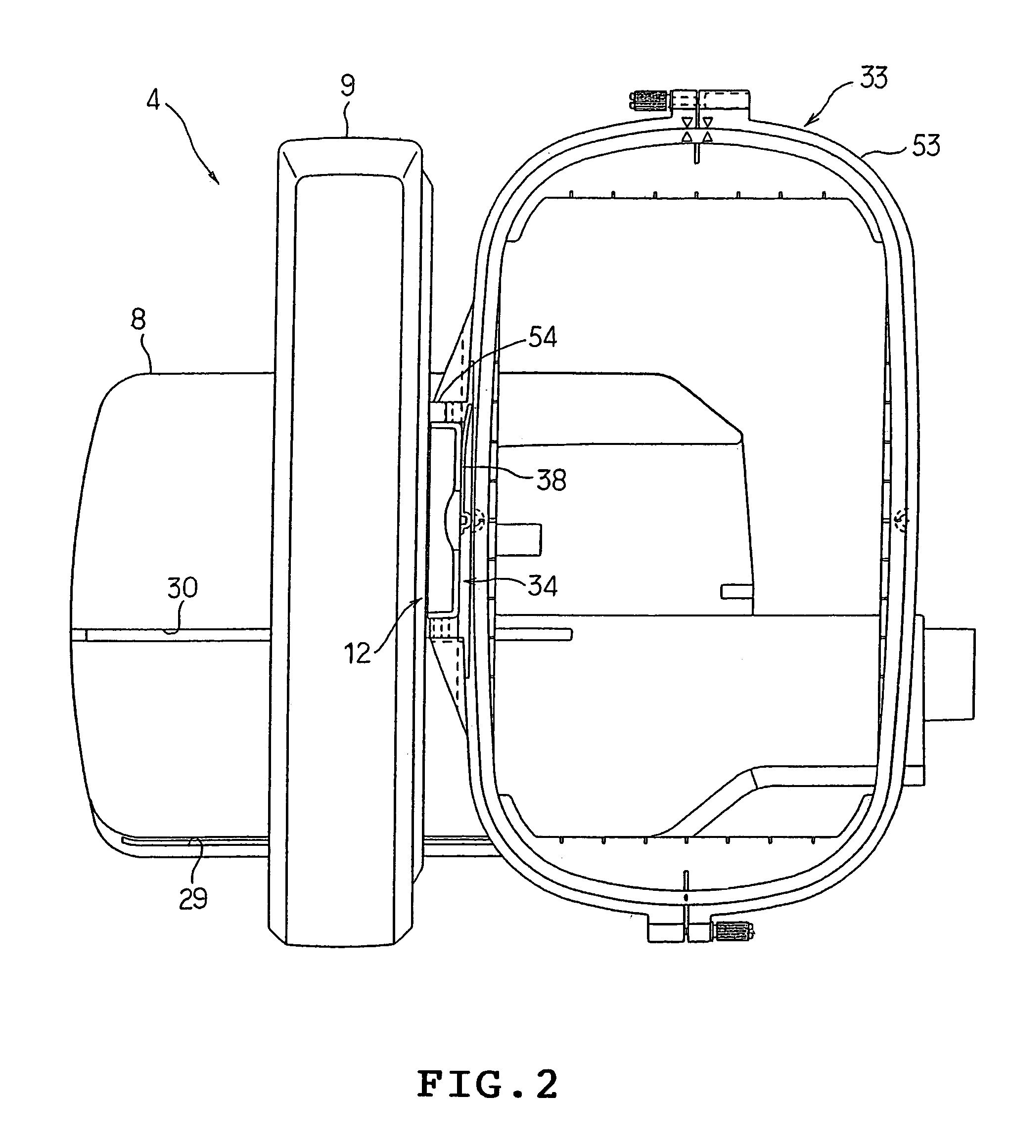
[0025]One embodiment of the present invention will be described with reference to the accompanying drawings. The present embodiment is applied to an electronic control type embroidering machine capable of sewing various embroidery patterns. First of all, in FIG. 1 showing the entire construction of the electronic control type embroidering machine, an embroidering machine M is provided with a bed 1, a column 2 erected at the right-hand end portion of the bed 1, and an arm 3 extending leftward from the upper end portion of the column 2 to confront the bed 1. At the left-hand end portion of the bed 1, there is disposed a free arm, on which an embroidery frame transfer device 4 is removably mounted.

[0026]At the head 3a of the arm 3, a needle bar 5 supporting a needle 5a and a presser bar 6 are supported vertically movably. The presser bar 6 is provided with a presser foot 7 at its lower end portion.

[0027]The bed 1 is provided therein with a thread catcher made of a rotating hook, althou...


PUM


Abstract

An attachment 52 comprises: a carriage connecting section 74 connected to a carriage 12 of an embroidery frame transfer device 4; and a metal fastener fixed to an attaching block 32 at the right-hand end portion of the carriage connecting section 74 and having a connecting section of a nonstandard embroidery frame 51 connected thereto. By connecting a connecting section 66 of the nonstandard embroidery frame 51 to the metal fastener 75 of the attachment 52 and by connecting the carriage connecting section 74 of the attachment 52 to the carriage 12, the nonstandard embroidery frame 51 can be mounted indirectly on the carriage 12. Thus, the nonstandard embroidery frame 51 of the type different in construction for attachment to the carriage 12 can be connected to the carriage 12.

Description

TECHNICAL FIELD[0001]The present invention relates to an embroidery frame transfer device having a transfer mechanism for transferring a carriage, on which an embroidery frame for holding a cloth to be embroidered is mounted, in two orthogonal directions, and an attachment for mounting the embroidery frame indirectly on the carriage.BACKGROUND ART[0002]Generally, the embroidery frame transfer device is provided with: an embroidery frame for holding a cloth to be embroidered; a carriage capable of mounting / demounting the embroidery frame; a Y-direction transfer mechanism for moving the carriage in the widthwise direction (or Y-direction) of a machine head portion; and an X-direction transfer mechanism for moving the carriage together with the Y-direction transfer mechanism in the longitudinal direction (or X-direction) of the machine head portion. By executing the sewing actions while moving the embroidery frame in the X- and Y-directions by the embroidery frame transfer device, an e...

Claims


Application Information

Patent Timeline
Patent Type & Authority Patents(United States)
IPC IPC(8): D05C9/04D05C9/00D05B39/00D05B21/00
CPCD05C9/04D05B21/00
Inventor SHOJI, YOSHIHISA
Owner BROTHER KOGYO KK
Why Eureka
Eureka Blog
Learn More