
Optical disk drive assembly that is rotatable with respect to a computer casing

a technology of optical disk drive and computer casing, which is applied in the field of computers, can solve the problems of time-consuming and inconvenient processing, and achieve the effect of decreasing the rotation speed

Inactive Publication Date: 2007-08-14
SAMSUNG ELECTRONICS CO LTD
View PDF21 Cites 52 Cited by
  • Summary
  • Abstract
  • Description
  • Claims
  • Application Information

AI Technical Summary

Benefits of technology

Facilitates easy replacement and upgrading of components by allowing the optical disk drive to be rotated outside the casing, reducing the complexity and time required for repairs and upgrades.

Problems solved by technology

This process is both time-consuming and inconvenient.

Method used


Image

  • Optical disk drive assembly that is rotatable with respect to a computer casing
  • Optical disk drive assembly that is rotatable with respect to a computer casing
  • Optical disk drive assembly that is rotatable with respect to a computer casing

Examples


Embodiment Construction

[0036]Reference will now be made in detail to the embodiments of the present invention, examples of which are illustrated in the accompanying drawings, wherein like reference numerals refer to like elements throughout. The embodiments are described below to explain the present invention by referring to the figures.

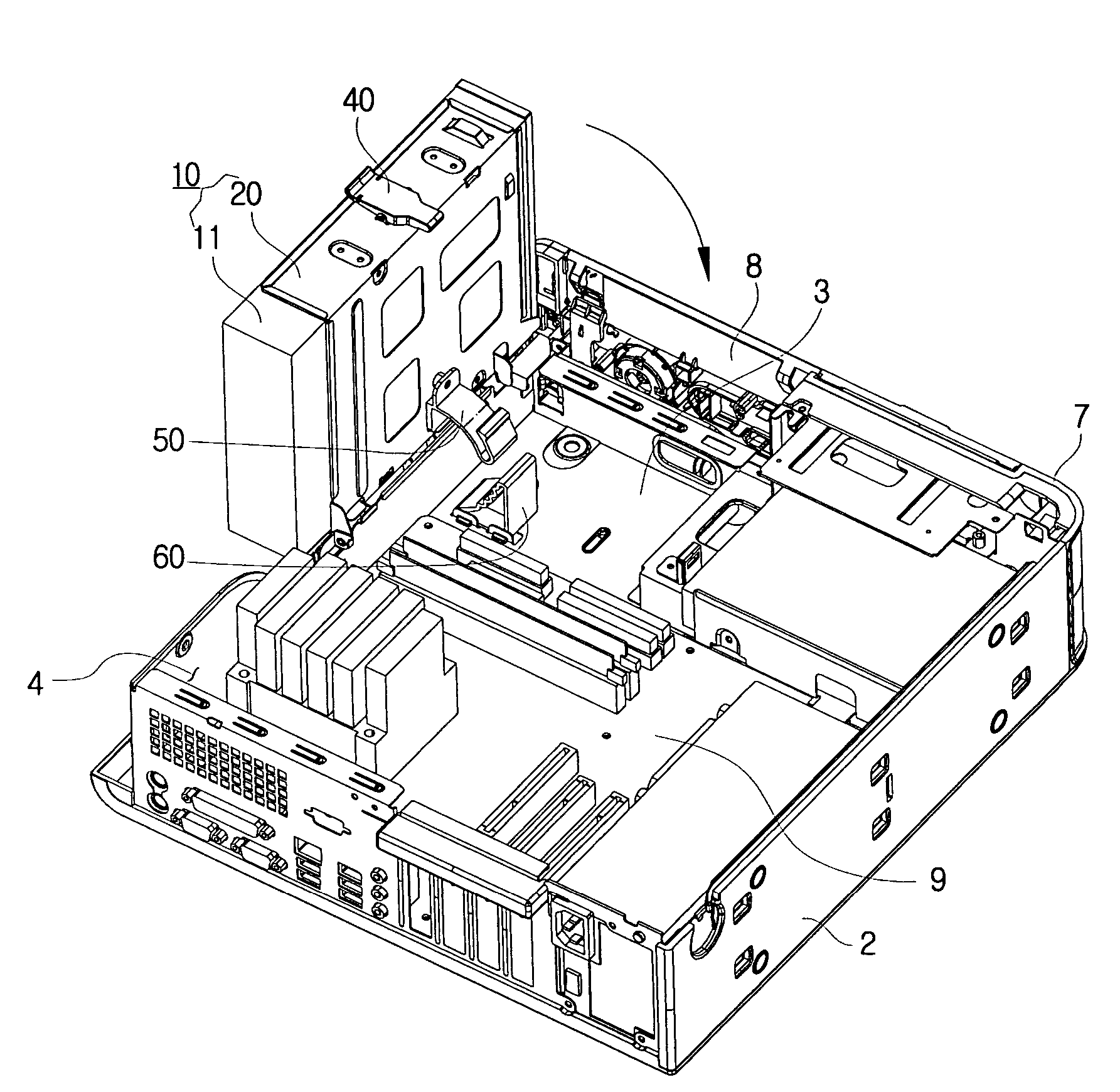
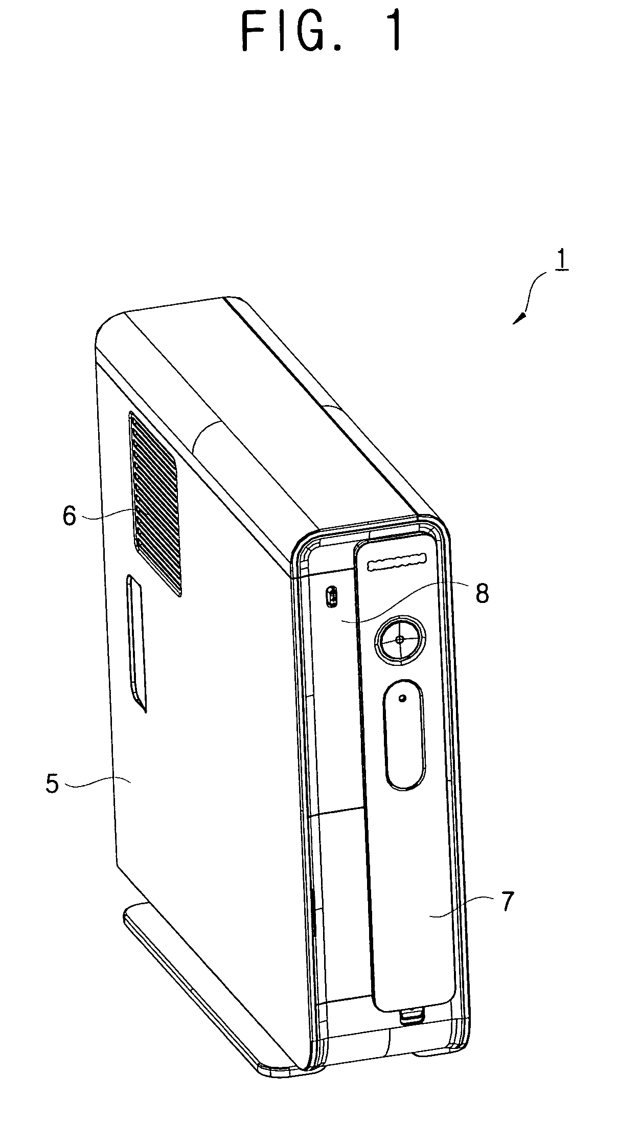
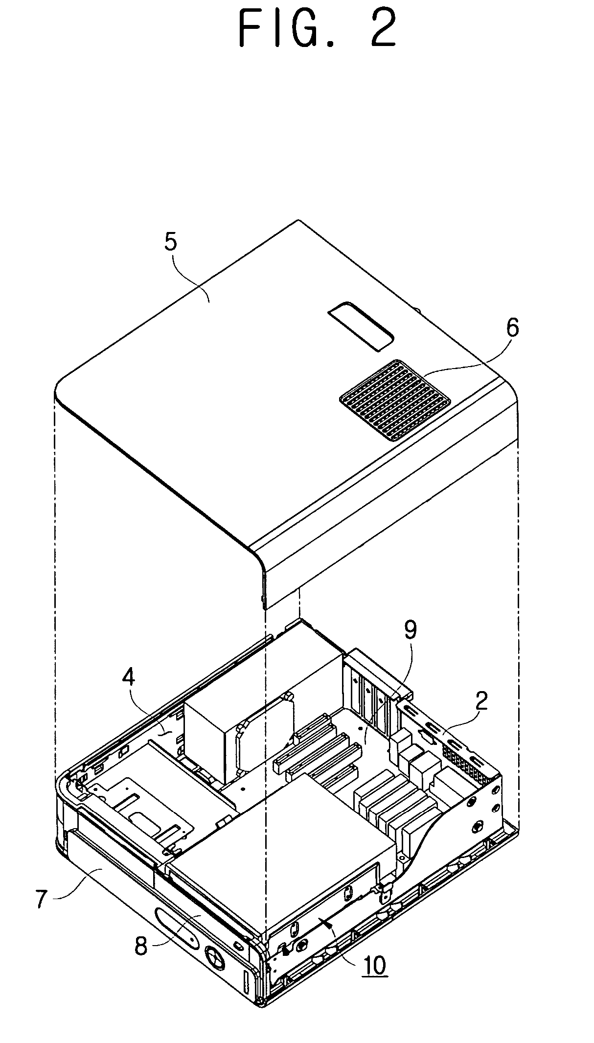
[0037]FIG. 1 is a perspective view of a computer according to an embodiment of the present invention, and FIG. 2 is a perspective view illustrating an optical disk drive according to FIG. 1 in an accommodated position. FIG. 3 is a perspective view illustrating an optical disk drive according to FIG. 2 in an ejected position. FIG. 4 is an exploded perspective view of the optical disk drive according to FIG. 3;

[0038]With reference to FIGS. 1-4, a computer according to an embodiment of the present invention comprises a computer main body 1, a monitor (not shown) displaying a picture on a screen, and an input apparatus (not shown) such as a mouse or a keyboard with which a use...


PUM

PropertyMeasurementUnit
rotation speedaaaaaaaaaa
distanceaaaaaaaaaa
poweraaaaaaaaaa

Abstract

A computer comprising: a main body casing accommodating a plurality of hardware components and comprising an entrance opening on a first side thereof; an optical disk drive assembly combined to the main body casing to rotate relative to the main body casing; and a hinge unit provided on a side of the entrance opening of the main body casing, and supporting the optical disk drive assembly to enable the optical disk drive assembly to rotate between an accommodated position where the optical disk drive assembly is accommodated in the main body casing and an ejected position where the optical disk drive assembly is ejected out of the main body casing through the entrance opening. Such a computer is easy for disassembling and assembling when the user repairs or upgrades because an optical disk drive assembly rotates between the accommodated position and the ejected position.

Description

CROSS-REFERENCE TO RELATED APPLICATIONS[0001]This application claims the benefit of Korean Patent Application No. 2003-067464, filed Sep. 29, 2003, in the Korean Intellectual Property Office, the disclosure of which is hereby incorporated herein by reference.BACKGROUND OF THE INVENTION[0002]1. Field of the Invention[0003]The present invention relates to a computer, and particularly to a computer comprising a rotatable optical disk drive assembly.[0004]2. Description of the Related Art[0005]As illustrated in FIG. 7, a computer generally comprises a casing 110, a peripheral device 121 provided in the casing 110, a computer main body 101 comprising a plurality of hardware components such as a main board installed with a central processing unit (CPU), a random access memory (RAM), and an extension card such as a graphic card or a sound card, and a monitor (not shown) receiving a video signal from the computer main body 101 and displaying a picture.[0006]The casing 110 comprises a front ...

Claims


Application Information

Patent Timeline
Patent Type & Authority Patents(United States)
IPC IPC(8): G11B33/12H05K5/02H05K7/16A47B81/00G06F1/16G11B33/02
CPCG11B33/022G11B33/121G11B33/124G06F1/16
Inventor LEE, SEUNG-WOON
Owner SAMSUNG ELECTRONICS CO LTD
Learn More