
Apparatus for measuring concentration of light-absorbing substance in blood

a technology of light-absorbing substances and measuring apparatuses, which is applied in the field of improving the measurement apparatus for the concentration of light-absorbing substances in blood, can solve the problems of not being considered, and achieve the effect of accurate measurement of concentration

Active Publication Date: 2007-08-14
NIHON KOHDEN CORP
View PDF13 Cites 34 Cited by
  • Summary
  • Abstract
  • Description
  • Claims
  • Application Information

AI Technical Summary

Benefits of technology

[0011]It is therefore an object of the invention to provide an apparatus capable of accurately measuring a concentration of a light-absorbing substance in blood through measurement based on pulse photometry.

Problems solved by technology

Hence, no consideration has been given to the light beam not passing through blood, which in turn causes an error.

Method used


Image

  • Apparatus for measuring concentration of light-absorbing substance in blood
  • Apparatus for measuring concentration of light-absorbing substance in blood
  • Apparatus for measuring concentration of light-absorbing substance in blood

Examples


first embodiment

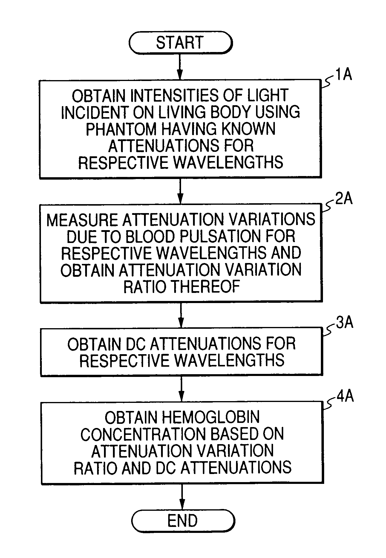
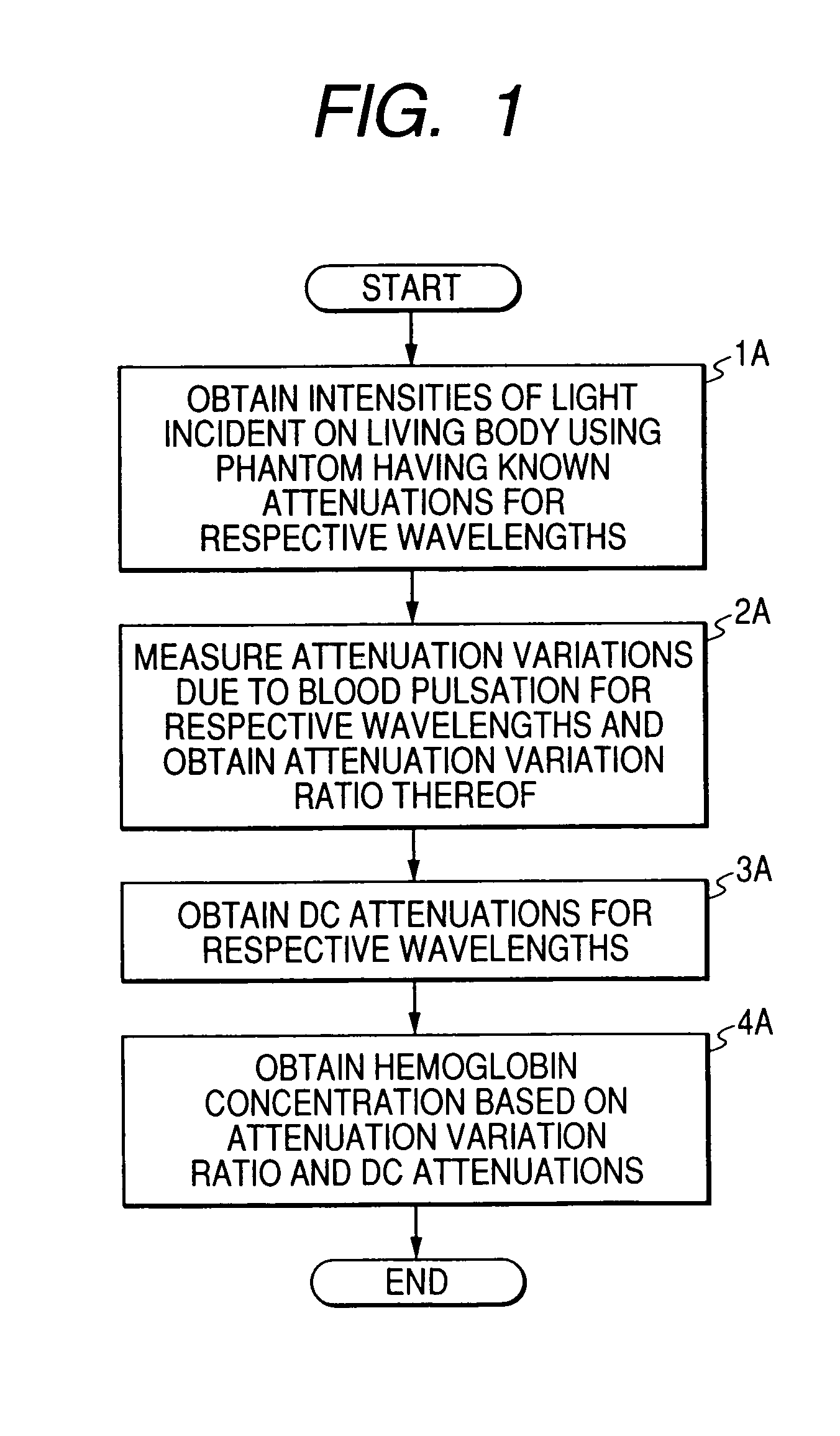
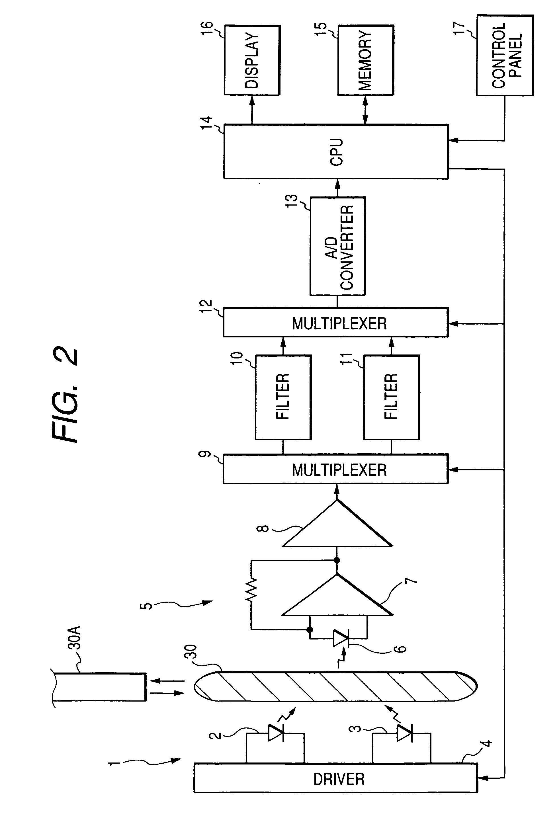
[0102]In step 1B, the intensity of the light incident on the living body 30 is measured. Specifically, the intensity of light radiated from the three LEDs 20a, 20b, and 20c of the probe onto the living body 30 is determined. As in the step 1A to be performed by the apparatus of the first embodiment, the operator places the phantom 30A at a predetermined position between the LEDs 20a, 20b, and 20c of the probe and the photodiode 60 and instructs the CPU 140 to start measuring the intensity of the incident light by operating the calibration switch. The CPU 140 performs calculating operation of the following equations by substituting the light intensities ltcal1, ltcal2, and ltcal3 of the three wavelengths of the light beams having passed through the phantom 30A, thereby determining incident light intensities lical1, lical2, and lical3 of three wavelengths and storing them into the memory 150.

lical1=ltcal1·exp(Af1)

lical2=ltcal2·exp(Af2)

lical3=ltcal3·exp(Af3)

Here, Af1, Af2, and Af3 deno...

second embodiment

[0121]However, as shown in FIG. 9, a program of processing to be performed by the CPU 140 differs from that described in the Moreover, the first wavelength assumes a value of 940 nm; the second wavelength assumes a value of 660 nm; and the third wavelength assumes a value of 805 nm. Operation of the apparatus will be described hereinbelow by reference to FIG. 9.

[0122]In step 1C, the intensity of the light incident on the living body 30 is measured. As in the case of step 1B to be performed by the apparatus of the second embodiment, the incident light intensities lical1, lical2, lical3 of the three light beams having different wavelengths are determined through use of the phantom 30A, and the thus-determined incident light intensities are stored in the memory 150.

[0123]In next step 2C, after having attached the probe to the living body 30, the operator infuses a dye into the blood of the living body 30. For instance, indocyanine green is used as a dye. A ratio between changes in the...


PUM

PropertyMeasurementUnit
wavelengthsaaaaaaaaaa

Abstract

An apparatus for measuring a concentration of a light-absorbing substance in blood is disclosed. A light emitter emits light beams to irradiate a living tissue, each of the light beams being associated with one wavelength which is absorbed by the blood. A first instrument measures first intensities of the light beams, which are to be incident on the living tissue. A second instrument measures second intensities of the light beams, which are transmitted through the living tissue. A first calculator calculates an attenuation variation ratio, which is a ratio of attenuation variations of the respective light beams due to variation of a volume of the blood caused by pulsation, based on the second intensities of the light beams. A second calculator calculates the concentration based on the first intensities, the second intensities, and the attenuation variation ratio.

Description

BACKGROUND OF THE INVENTION[0001]The present invention relates to an improvement in an apparatus for measuring a concentration of a light-absorbing substance in blood which employs pulse photometry as its operating principle: such as a pulse oximeter or an apparatus for measuring a pulse dye-dilution curve.[0002]Pulse photometry goes beyond a pulse oximeter and is currently employed as a pulse dye dilution method. This method is made commercially practical as an apparatus for measuring a cardiac output, a circulating blood volume, a blood plasma disappearance rate of indocyanine green (ICG), and ICG clearance by administering a dye called ICG into blood and determining the concentration of the ICG in blood. This method is described in detail in the following references: Takehiko Iijima, et al. Cardiac output and circulating blood volume analysis by pulse dye-densitometry. J Clin Monit 1997; 13: 81-89; Takasuke Imai, et al. Measurement of cardiac output by pulse dye-densitometry usin...

Claims


Application Information

Patent Timeline
Patent Type & Authority Patents(United States)
IPC IPC(8): A61B5/00G01N21/27A61B5/145A61B5/1455G01N21/31G01N21/35G01N21/3577G01N21/359
CPCA61B5/14551G01N2021/3144
Inventor TAKAMURA, YOSHIAKIKOBAYASHI, NAOKITAKEDA, SUNAOUSUDA, TAKASHI
Owner NIHON KOHDEN CORP
Learn More