
Optical interleaver

a technology of optical interleavers and interleavers, applied in the field of optical communication, can solve the problems of limited number of channels that can be carried in a single optical fiber, increased capacity demand may still adversely affect the signal quality during transmission, and exceedingly difficult to maintain signal integrity

Inactive Publication Date: 2007-08-14
II VI DELAWARE INC
View PDF34 Cites 5 Cited by
  • Summary
  • Abstract
  • Description
  • Claims
  • Application Information

AI Technical Summary

Problems solved by technology

However, as the communication capacity is further increased to transmit greater amounts of information at greater rates over fiber, maintaining signal integrity can be exceedingly challenging.
While transmission of information via an optical medium has offered significant improvements in information transmission, increased demand for capacity may still adversely impact signal quality during transmission.
For example, the number of channels that can be carried in a single optical fiber is limited by cross-talk, narrow operation bandwidth of optical amplifiers, and optical fiber non-linearities.
Among other difficulties, the decrease in channel spacing makes separating the plurality of optical channels more challenging.
As can be appreciated, meeting these performance requirements of ever-increasing demand is a technical and practical challenge.
These environmental factors can adversely impact the performance of the devices.
One deleterious environmental factor is the ambient temperature.
This wavelength drift can cause wavelength channel overlap.
In the closely spaced channels of ITU grids discussed above, optical system performance may be adversely impacted.
While it may be possible to control the ambient temperature surrounding the WDM device, this generally requires rather elaborate climate control devices, which can be relatively complex and expensive.
Moreover, these devices do not ensure the particular elements of a WDM are immune to temperature fluctuations.
As such, in addition to adding complexity and expense, known active temperature control schemes may be unreliable.

Method used


Image

  • Optical interleaver
  • Optical interleaver
  • Optical interleaver

Examples


Embodiment Construction

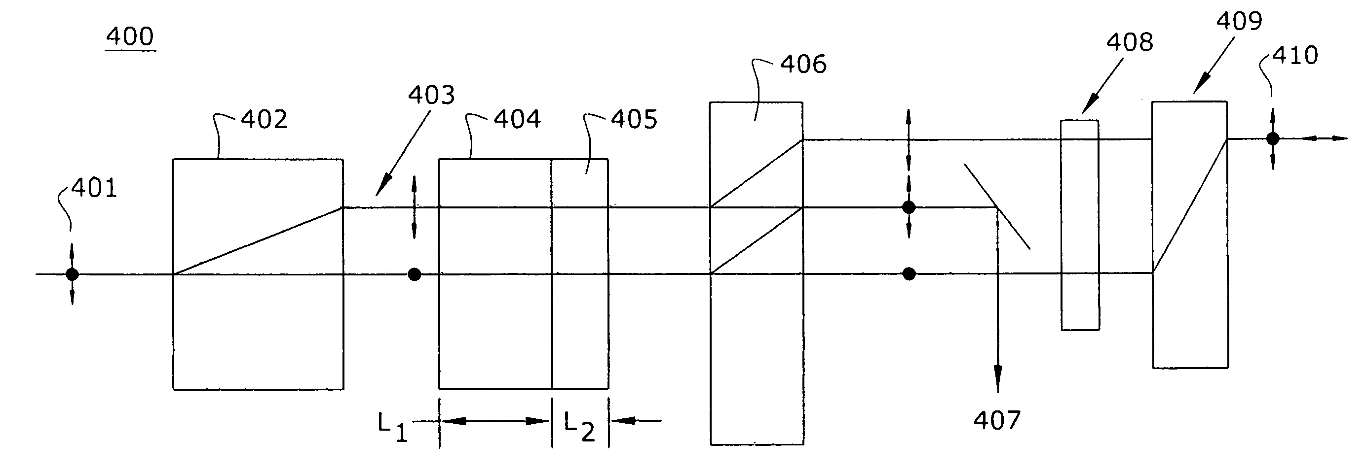
[0022]The invention will now be described more fully with reference to the accompanying drawing figures, in which exemplary embodiments are shown. In the following detailed description, for purposes of explanation and not limitation, exemplary embodiments disclosing specific details are set forth in order to provide a thorough understanding of the present invention. However, it will be apparent to one having ordinary skill in the art having had the benefit of the present disclosure, that the present invention may be practiced in other embodiments that depart from the specific details disclosed herein. Moreover, descriptions of well-known devices, methods and materials may be omitted so as to not obscure the description of the present invention.

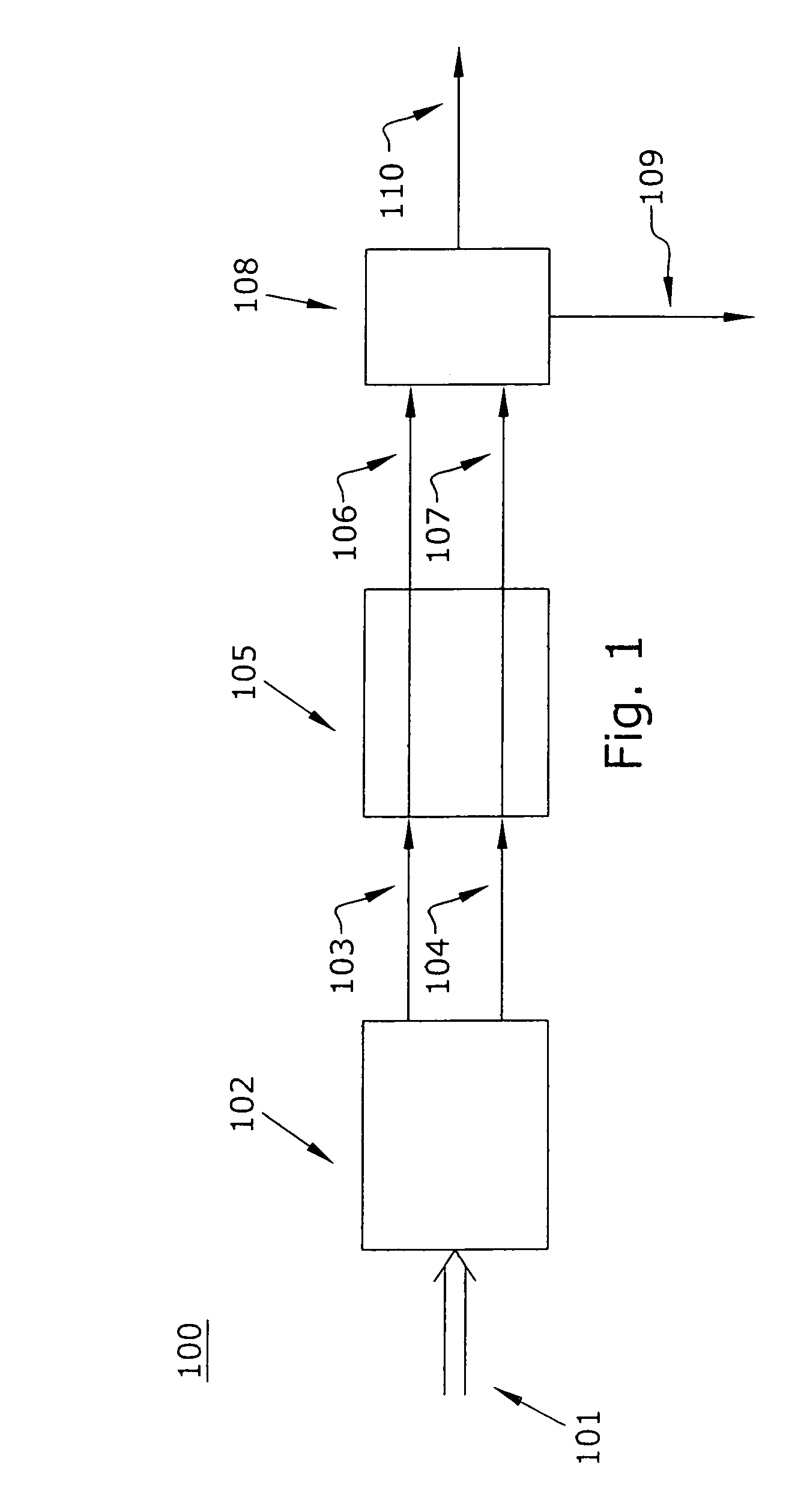
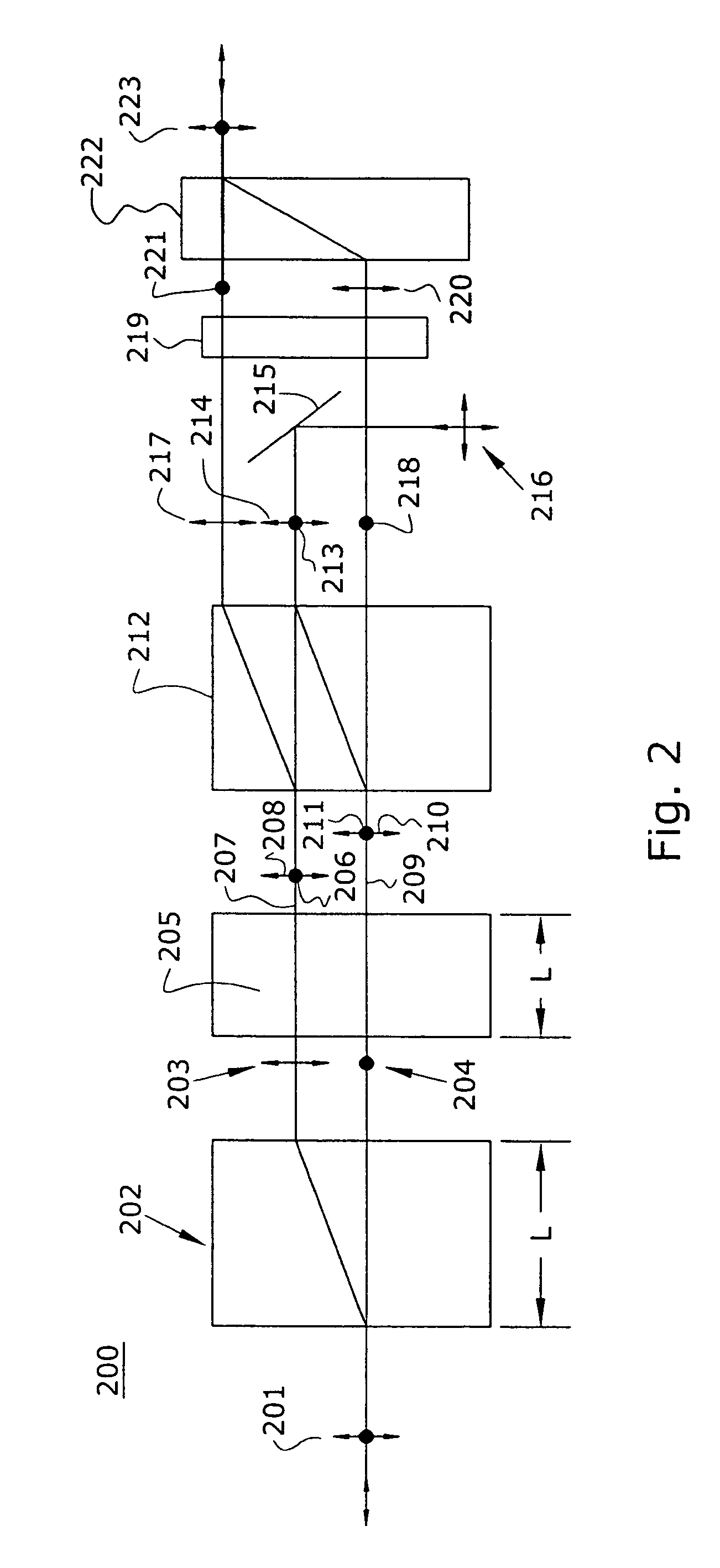
[0023]Briefly, the invention is drawn to a method and apparatus for interleaving / deinterleaving optical signals based on polarization inteferometry. Illustratively, the input optical signal from an input port has a known channel frequency peri...


PUM

PropertyMeasurementUnit
wavelength spacingaaaaaaaaaa
center wavelengthaaaaaaaaaa
center frequencyaaaaaaaaaa

Abstract

In accordance with an exemplary embodiment of the present invention, an optical device includes an interleaver / deinterleaver, which includes a passive thermal compensator, wherein an optical signal which transverses the optical device undergoes substantially no temperature induced frequency drift over a desired temperature range.

Description

CROSS-REFERENCE TO RELATED APPLICATIONS[0001]This application is a divisional of U.S. patent application Ser. No. 10 / 112,624, filed Mar. 28, 2002 now U.S. Pat. No. 6,956,988, which is herein incorporated by reference in its entirety.[0002]U.S. patent application Ser. No. 10 / 112,624 is a continuation-in-part application under 35 USC § 120 of U.S. patent application Ser. No. 10 / 103,469 filed Mar. 20, 2002 and entitled “Tunable Optical Filter,” now abandoned, which is a continuation of U.S. patent application Ser. No. 09 / 356,217 filed Jul. 16, 1999, now U.S. Pat. No. 6,370,286, issued Apr. 9, 2002, which claims the benefit of U.S. Provisional Application No. 60 / 097,464, filed Aug. 21, 1998. The present application also claims priority under 35 USC § 119(e) from U.S. Provisional Application Ser. Nos. 60 / 279,695 and 60 / 279,696, entitled “Optical Interleaver”, and “Optical Interleaver With Passive Thermal Effect Compensation,” respectively, and filed on Mar. 30, 2001. The disclosures of a...

Claims


Application Information

Patent Timeline
Patent Type & Authority Patents(United States)
IPC IPC(8): G02B6/28G02B5/30G02B6/293C07C237/42C07C255/57C07C257/18C07D205/04C07D211/22C07D211/26C07D211/34C07D211/62C07D213/75C07D233/22C07D233/54C07D295/13C07D295/195C07D307/54C07D401/12C07D401/14C07D403/12C07D405/12G02B6/26G02B6/34
CPCC07C237/42C07C255/57C07C257/18C07D205/04C07D211/22C07D211/26C07D211/34C07D211/62C07D213/75C07D233/22C07D233/64C07D295/13C07D295/195C07D307/54C07D401/12C07D401/14C07D403/12C07D405/12G02B6/272G02B6/2766G02B6/29302G02B6/2935G02B6/29386G02B6/29395G02B6/2706G02B6/2746G02B6/2773
Inventor AMIN, JAYMINKROL, MARK F.WU, QI
Owner II VI DELAWARE INC
Learn More