
Series active filtering power line conditioner

a filtering power line conditioner and active filter technology, applied in the field of series active regulators, can solve the problems of harmonic distortion, spurious noise, random noise components, etc., and achieve the effect of effectively subtracting voltage imperfections and stabilizing without compromising bandwidth

Inactive Publication Date: 2007-08-14
GABRIEL PATENT TECH
View PDF5 Cites 26 Cited by
  • Summary
  • Abstract
  • Description
  • Claims
  • Application Information

AI Technical Summary

Benefits of technology

[0021]A power line conditioner operated in a method according to the present invention utilizes a series buck-boost voltage regulator as a filter for removing unwanted impurities from a source of alternating current power. The preferred embodiment of the apparatus includes a transformer and an active filter coupled in series to a power distribution network. The power distribution network includes a voltage source that induces input currents at a first end of the power distribution network. Nonlinear loads and other conditions on the power distribution network cause harmonic, spurious, and random noise components to corrupt the power signals. The active filter of the invention uses a monochromatic reference derived from the incoming AC power voltage which is prepared by stripping off unwanted harmonics and noise and regulating amplitude to a predetermined value. A feedback control system is configured to operate in series with a secondary winding of the transformer so as to effectively subtract voltage imperfections from the incoming AC. The control loop is compensated in such a way that it is stabilized without compromising bandwidth.

Problems solved by technology

Nonlinear loads and other conditions on the power distribution network cause harmonic, spurious, and random noise components to corrupt the power signals.

Method used


Image

  • Series active filtering power line conditioner
  • Series active filtering power line conditioner
  • Series active filtering power line conditioner

Examples


Embodiment Construction

[0046]In the description that follows, like reference numerals refer to corresponding parts throughout the several views of the drawings.

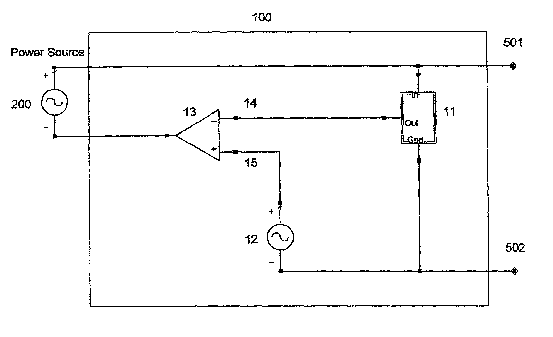
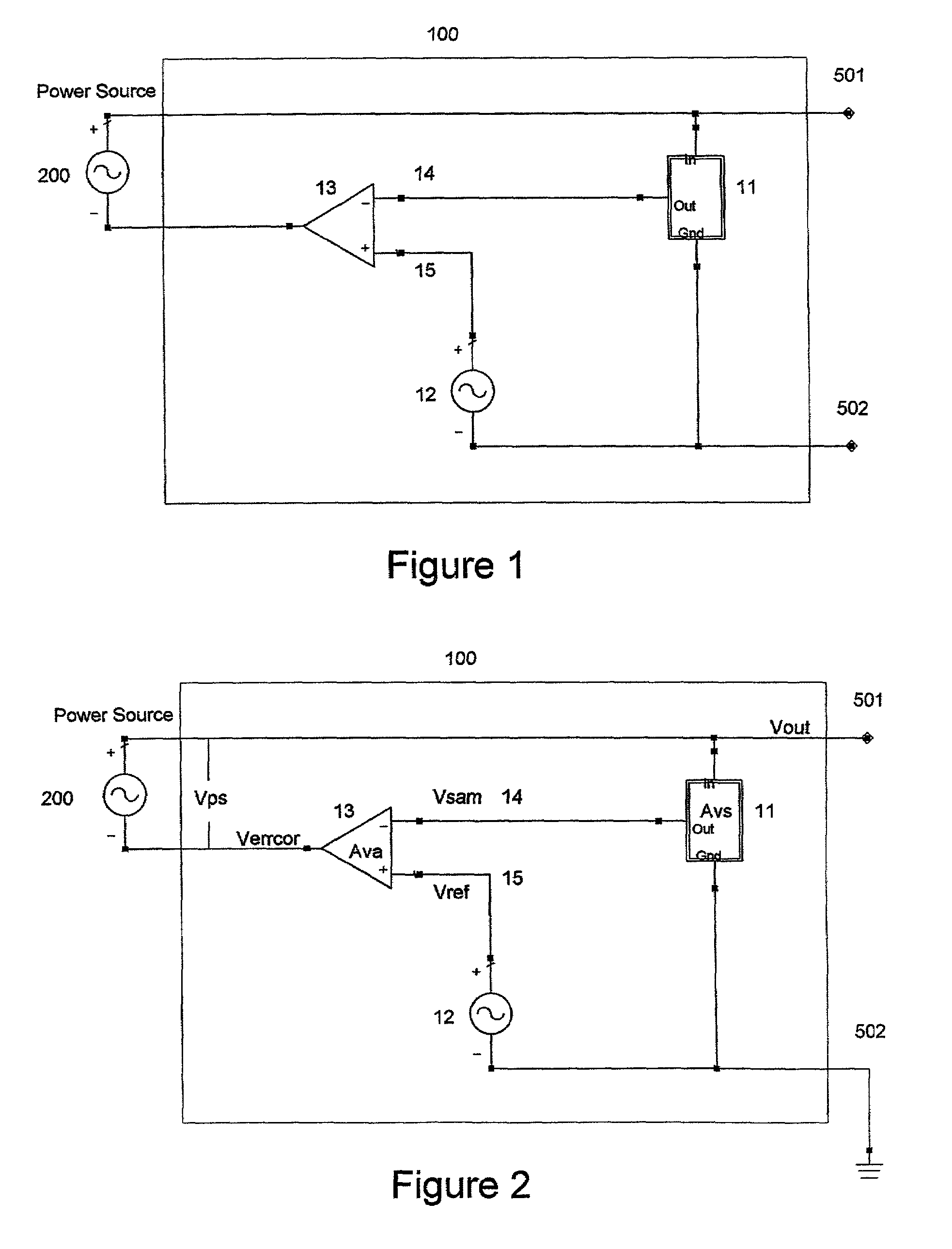
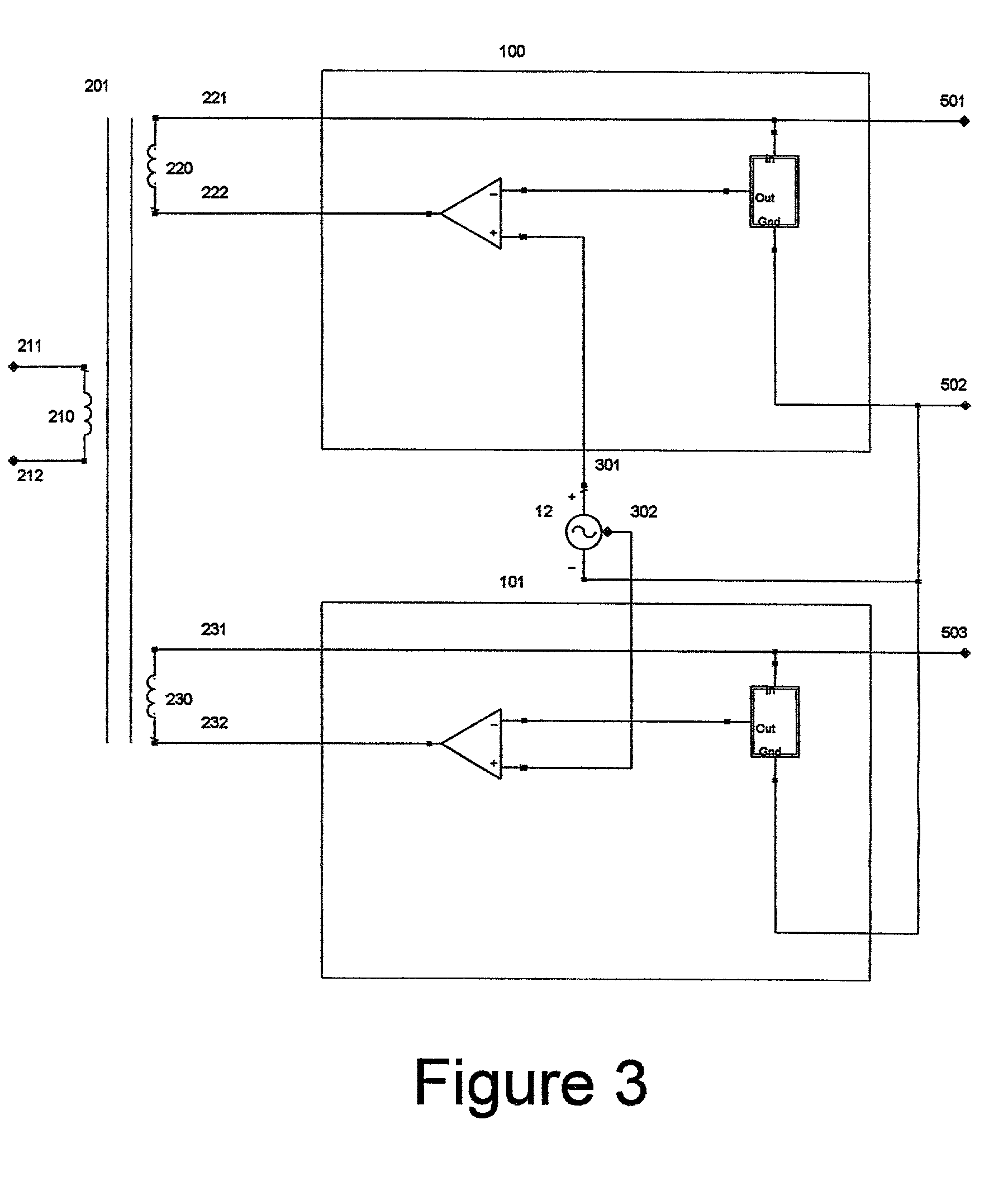
[0047]FIG. 1 depicts elements associated with an embodiment of the present invention. In general, the invention is directed to a series configured error correction feedback control system 100 which operates with other familiar components and a source of alternating current power 200. The feedback control system 100 is composed of sampler 11, voltage reference 12, and amplifier 13. All voltages describing the behavior of control system 100 are taken with respect to output 502, which is typically tied to system ground. It is a general characteristic of the invention that sampled voltage is compared with a reference voltage by an amplifier. It is a further characteristic of the invention that the sampled voltage appears at an input of an amplifier as negative feedback, whereby the amplifier acts in series with an alternating current power source to pr...


PUM


Abstract

The apparatus includes a series active continuous time voltage regulator operating in conjunction with a alternating current power source and one or more loads. The alternating current power source is a voltage source that induces currents at a first end of the apparatus. At a second end of the apparatus one or more loads consume power from the apparatus. The series buck-boost regulator is composed of a pure monochromatic voltage source of frequency equal to that of the alternating current power source, and of constant phase with respect to the alternating current power source. The regulator is further composed of a sampling network that provides a scaled continuous time sample of the voltage delivered by the power conditioner to the loads. Finally, the regulator is composed of a high gain differential amplifier. The components of the regulator are configured to operate as a continuous time feedback control system that generates an error correction voltage that, when added to the voltage of the alternating current power source, results in an output voltage from the power conditioner that is a scaled replica of the monochromatic reference voltage. As a result, the voltage delivered by the power conditioner to the loads is substantially corrected of spectral impurities and impervious to the specific conditions of the alternating current power source or of the loads.

Description

CROSS REFERENCE TO RELATED APPLICATIONS [0001]This application is a continuation of co-pending U.S. Ser. No. 60 / 267,399, filed on Feb. 7, 2001. The priority of the prior application is expressly claimed and its disclosure is hereby incorporated by reference in its entirety.FIELD OF THE INVENTION [0002]This invention relates generally to power conditioners and methods which operate in the presence of unconditioned alternating current power, and more particularly to series active regulators used as active filters. These systems act to remove spectral impurities from the alternating current power line so as to provide power that is substantially sinusoidal and devoid of harmonic, spurious and random noise components.BACKGROUND OF THE INVENTION [0003]Power conditioning circuits are used to remove unwanted voltages and currents from alternating current voltage sources intended for supplying operating power to electronic equipment. Power conditioning sometimes refers to surge and spike pr...

Claims


Application Information

Patent Timeline
Patent Type & Authority Patents(United States)
IPC IPC(8): G05F3/02H02J3/01H02M1/12
CPCH02J3/01H02M1/12H02M2001/0012Y02E40/22H02M1/0012Y02E40/20
Inventor VICE, MICHAEL WENDELL
Owner GABRIEL PATENT TECH
Learn More