
Split-transaction bus intelligent logic analysis tool

a logic analysis and split-transaction bus technology, applied in multiplex communication, data switching networks, instruments, etc., can solve the problems of not providing real-time analysis capability, not real-time solution, and not allowing real-time triggering, so as to achieve efficient triggering capability

Active Publication Date: 2007-08-07
ADVANCED MICRO DEVICES INC
View PDF19 Cites 29 Cited by
  • Summary
  • Abstract
  • Description
  • Claims
  • Application Information

AI Technical Summary

Benefits of technology

[0010]Accordingly, in one embodiment, an improved protocol analyzer tool and method has a bus synchronizer, a decoder and a logic analysis function. The bus synchronizer is configured to receive link traffic and frame the link traffic into a plurality of framed packets, the plurality of framed packets including a plurality of request packets and a plurality of response packets. The decoder is configured to receive the plurality of framed packets and decode them into decoded packets, wherein at least one of the decoded packets includes information from a request packet and information from a corresponding response packet. The logic analysis function is configured to receive the decoded packets and initiate a trigger action on receipt of one of the decoded packets. Thus, the request packets and corresponding response packets are decoded for logic analysis providing efficient triggering capability.

Problems solved by technology

However, because the data is stored and later post-processed, the analysis is not a real time solution and typically doesn't allow real-time triggering on complex events.
However, these logic analyzers typically only monitor a bus and decode the signals according to the bus protocol, for example, converting a 32-bit value into a command or address.
However, this does not provide real time analysis capability and thus triggering on specific events is unavailable.

Method used


Image

  • Split-transaction bus intelligent logic analysis tool
  • Split-transaction bus intelligent logic analysis tool
  • Split-transaction bus intelligent logic analysis tool

Examples


Embodiment Construction

)

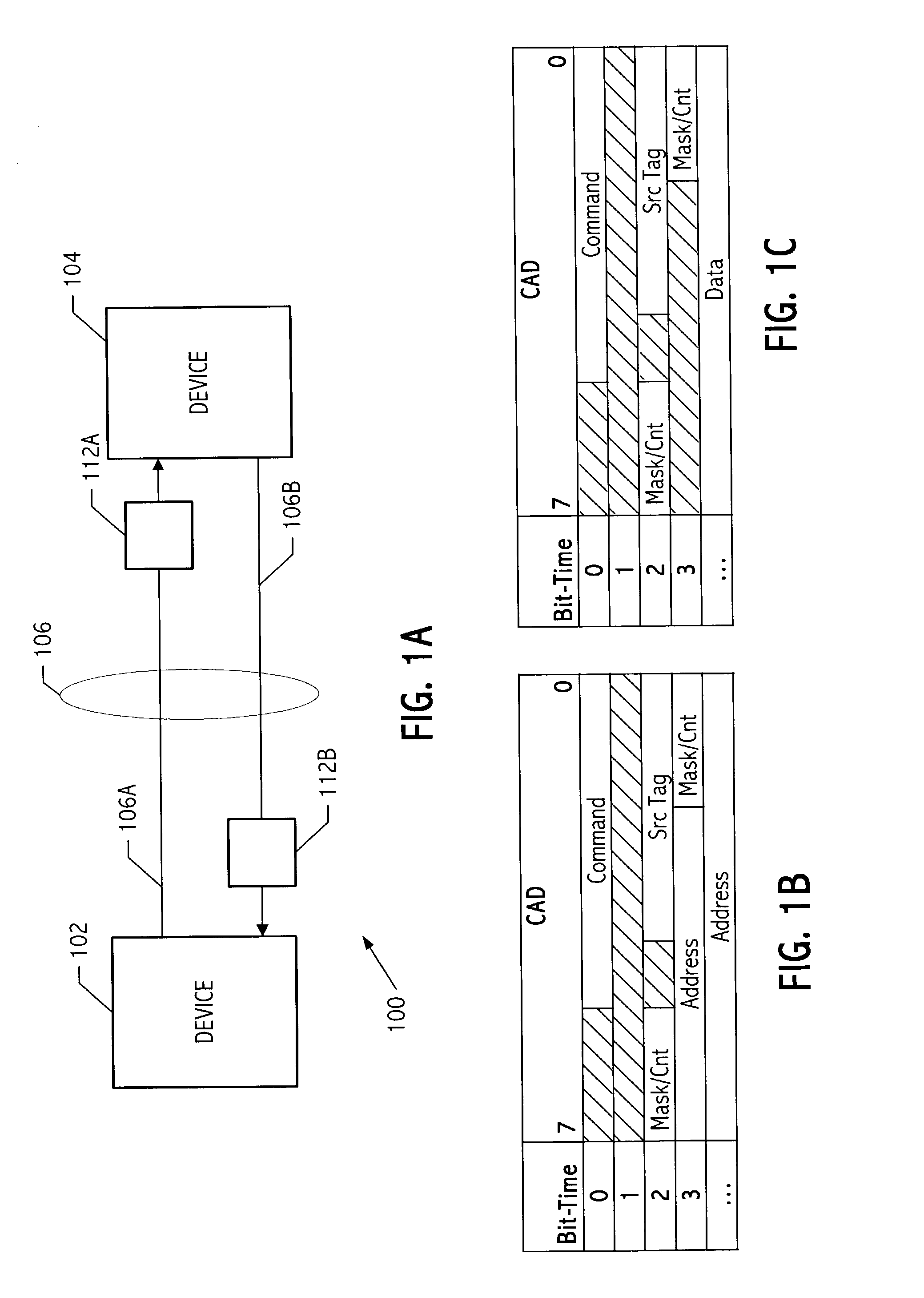
[0029]FIG. 1A illustrates an exemplary system 100 including a split-transaction bus. A device 102 is coupled to a device 104 via a split-transaction bus 106. Split-transaction bus 106 includes a downstream data flow 106A, also referred to as link A, and an upstream data flow 106B, also referred to as link B. Probe connection points 112A and 112B are coupled to downstream data flow 106A and upstream data flow 106B, respectively. Probe connection points 112 can be, for example, inline with each link (as shown), or as a stub connection (not shown). Link signals typically include link traffic such as clock, control, command, address and data information and link sideband signals that qualify and synchronize the traffic flowing between device 102 and device 104.

[0030]According to one embodiment of the invention, device 102 can be a processor, for example, an AMD Opteron™ micro-processor, device 104 can be a bridging device, for example, an AMD 8111 HyperTransport™ (HT) IO Hub, and split...


PUM


Abstract

An improved split-transaction bus intelligent logic analysis tool has a bus synchronizer, a decoder and a logic analysis function. The bus synchronizer is configured to receive link traffic and frame the link traffic into a plurality of framed packets, the plurality of framed packets including a plurality of request packets and a plurality of response packets. The decoder is configured to receive the plurality of framed packets and decode the plurality of framed packets into decoded packets, wherein at least one of the decoded packets includes information from a request packet and information from a corresponding response packet. The logic analysis function is configured to receive the decoded packets and initiate a trigger action on receipt of one of the decoded packets.

Description

CROSS-REFERENCE TO RELATED APPLICATION(S)[0001]This application is related to U.S. patent application Ser. No. 10 / 229,583 entitled “SPLIT-TRANSACTION BUS DECODER,” naming Sanjiv K. Lakhanpal, Steven R. Klassen, and Mark D. Nicol as co-inventors, and filed on Aug. 28, 2002. The related application is incorporated herein by reference in its entirety.BACKGROUND[0002]1. Field of the Invention[0003]This invention relates to tools for analysis of electronic circuits and more particularly to an intelligent analysis tool that interprets bus protocols and associates request packets and response packets on a split-transaction bus.[0004]2. Description of the Related Art[0005]Logic analyzers have been used for years to help debug and evaluate electronic circuits. Typically, probes or connectors are attached to signals on an electronic circuit, for example, a printed circuit board (PCB). The activities of the signals are monitored and displayed on a logic analyzer's screen or computer screen as ...

Claims


Application Information

Patent Timeline
IPC IPC(8): H04L12/28G06F13/00G06F15/173H04J3/06
CPCH04L43/18
Inventor LAKHANPAL, SANJIV K.KLASSEN, STEVEN R.NICOL, MARK D.
Owner ADVANCED MICRO DEVICES INC
Learn More