
Work-vehicle cabin having air-conditioning unit

a technology for working vehicles and cabins, applied in the field of work-vehicle cabins, can solve the problems of air leakage from the connection, compromising the roominess of the cabin and the driver's comfort, etc., and achieve the effect of maximizing the width of the rear window

Active Publication Date: 2007-08-07
KUBOTA LTD
View PDF30 Cites 32 Cited by
  • Summary
  • Abstract
  • Description
  • Claims
  • Application Information

AI Technical Summary

Benefits of technology

The present invention provides an improved air-conditioning duct construction with reduced risk of air leak, while securing maximum free space inside the cabin. It also prevents the inadvertent switchover of the damper when an operator gets in / out of the cabin and restricts blowing-in of raindrops or the like when the windows provided on the opposed lateral sides of the cabin are open to the outside. The roof unit includes an inner roof portion and an outer roof portion, and the lateral air-conditioning duct is fixed between these inner and outer roof portions without requiring special fixing tools or means. The forward air-conditioning duct and the lateral air-conditioning duct are connected to each other through a cylindrical portion with a cutout, and a cover member fixes the cutout, reducing displacement and air leak. The air-communicating passage guides air introduced through the outdoor air introducing opening to the air-conditioning unit, and the air-supply opening feeds conditioned air to the inside of the cabin. The air circulating opening communicates between the inside of the cabin and the air communicating passage.

Problems solved by technology

As a result, the rear end the downwardly bulging ceiling portion extends to a position upwardly of a driver's seat, thus compromising roominess of the cabin and driver's comfort.
This connecting construction using inclined flanges tends to result in displacement between the flanges, which leads eventually to air leak from the connection.

Method used


Image

  • Work-vehicle cabin having air-conditioning unit
  • Work-vehicle cabin having air-conditioning unit
  • Work-vehicle cabin having air-conditioning unit

Examples


Embodiment Construction

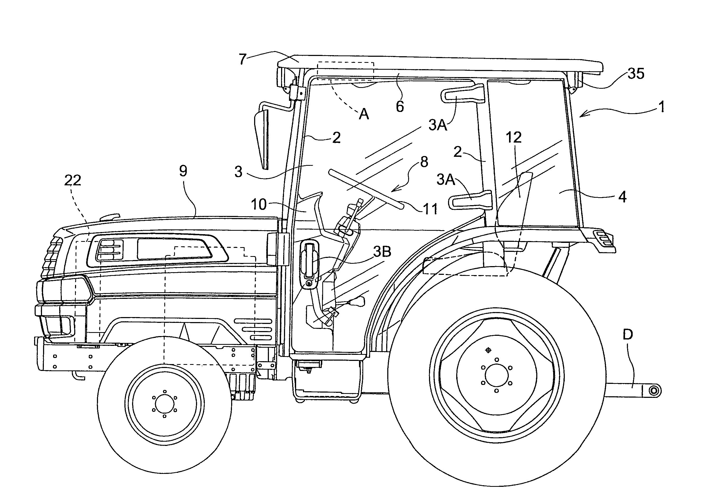
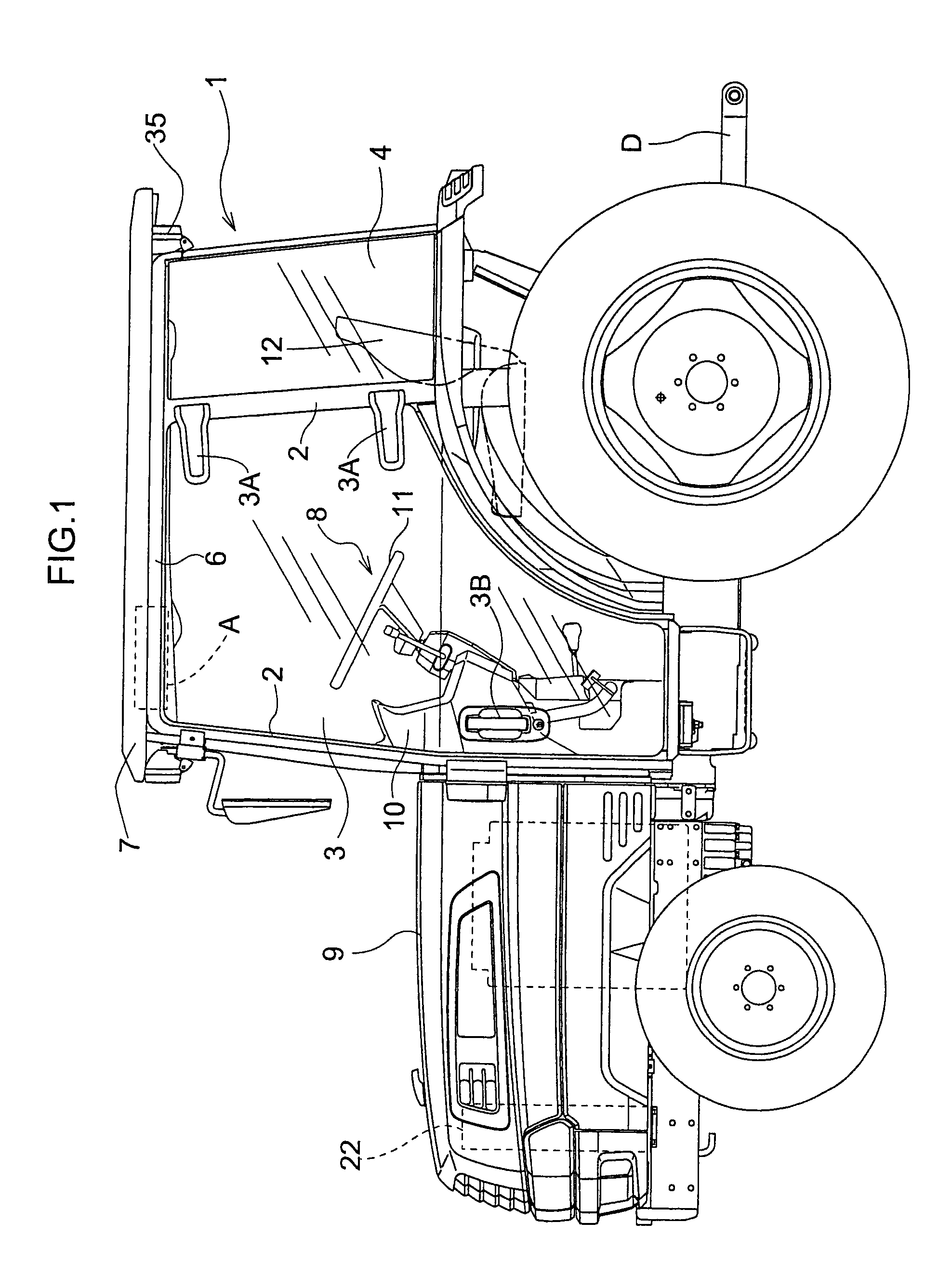
[0065]As an example of a work vehicle, an agricultural tractor will be described. A cabin 1 of this agricultural tractor, as shown in FIGS. 1 and 6, includes a plurality of struts 2 for the cabin, a driver's access side door 3 having a transparent glass face covering a portion surrounded by the struts 2, a rear side window 4, a rear window 5, an upper frame 6 extending over the top plane of the respective struts 2, and a roof unit 7 mounted on the upper frame 6.

[0066]Inside the cabin 1, there is provided a driver's section 8. In this driver's section 8, there is disposed a steering wheel 11 mounted on a handle post 10 located adjacent an engine hood 9, and a driver's seat 12 is disposed behind the handle post 11.

[0067]The roof unit 7 incorporates therein an air-conditioning unit A for conditioning air inside the cabin 1. To the rear end of the agricultural tractor, there is mounted a lift link mechanism for lifting up / down an implement such as a cultivator relative to the traveling ...


PUM


Abstract

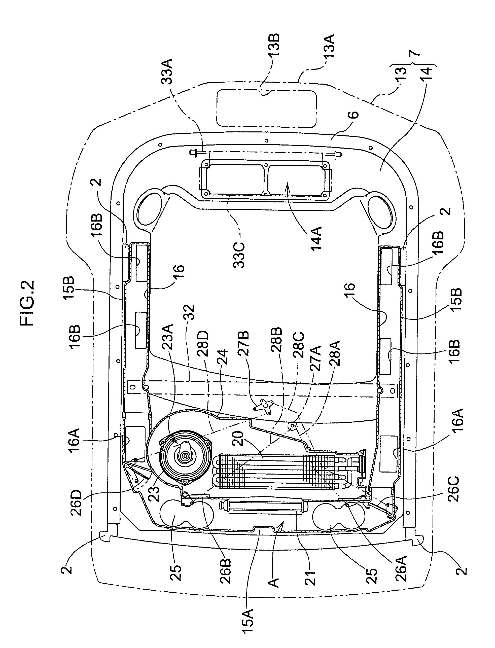
A work-vehicle cabin having an air-conditioning unit is disclosed. The cabin includes a roof unit, a downwardly bulging ceiling portion constituting a part of the roof unit, a heater provided in the ceiling portion, an evaporator provided in the ceiling portion and arranged adjacently rearwardly of the heater, and a pair of forward air-supply openings provided in the ceiling portion and respectively disposed laterally of the heater for feeding conditioned air to the inside of the cabin.

Description

BACKGROUND OF THE INVENTION[0001]1. Field of the Invention[0002]The present invention relates to a work-vehicle cabin having an air-conditioning unit mounted to a ceiling portion of the cabin, the air-conditioning unit having a heater and an evaporator.[0003]2. Description of the Related Art[0004]A work-vehicle cabin having an air-conditioning unit is known from Japanese Patent Application “Kokai” No.: Hei. 8-216672 (see paragraph [0020], FIGS. 1 and 2). In this, a downwardly bulging ceiling portion includes a forward air-supply opening, rearwardly of which there is disposed an air-conditioning unit for feeding conditioned air to this forward air-supply opening. In the case of this conventional cabin, the forward air-supply opening and the air-conditioning unit are disposed one behind the other. So, the air-conditioning unit projects rearward significantly. As a result, the rear end the downwardly bulging ceiling portion extends to a position upwardly of a driver's seat, thus compro...

Claims


Application Information

Patent Timeline
Patent Type & Authority Patents(United States)
IPC IPC(8): B60H1/00B62D33/06
CPCB60H1/00378B60H1/00535B62D33/0617B60H1/00849B60H1/34B60H2001/00242B60H2001/00714
Inventor ICHIKAWA, NOBUSHIGENAKAMURA, KENTARO
Owner KUBOTA LTD
Learn More