
Method for designing mold, mold, and molded product

a technology of molds and products, applied in the field of molds and molds, can solve the problems of long manufacturing period, difficult prediction and quantification of correction values, etc., and achieve the effects of short time, short manufacturing period, and efficient design

Inactive Publication Date: 2007-07-31
HOYA CORP
View PDF16 Cites 6 Cited by
  • Summary
  • Abstract
  • Description
  • Claims
  • Application Information

AI Technical Summary

Benefits of technology

The present invention relates to a mold designing method for correcting the shape of a molded product, such as an optical lens, by adding a proper shape correction to the mold. The invention addresses the difficulty of accurately predicting the shape of the molded product when using a mold designing method that takes into consideration factors such as mold shrinkage, stress, and the shape of the optical lens. The invention provides a method for designing a mold that can produce a molded product with the desired shape, while also accounting for the complex shape of the molded product, such as a spectacle lens. The invention also addresses the issue of predicting the transformation value with shrinkage taken into consideration, and the influence of noise on the correction value. The invention aims to improve the precision and efficiency of mold designing and production.

Problems solved by technology

Correction values of the molding surfaces of these molds differ for each refractive power of optical lenses, lens material and shape of the design curved surface, and have complicated tendency by combination of them.
Further, prediction and quantification of the correction value are difficult, and a skill is required in determination of a proper correction value.
For this reason, in production of molds, the operation of shape correction for each mold as described above is performed, and therefore, a long manufacturing period is required.

Method used


Image

  • Method for designing mold, mold, and molded product
  • Method for designing mold, mold, and molded product
  • Method for designing mold, mold, and molded product

Examples


first embodiment (fig.1 to fig.10)

[0056][A] First Embodiment (FIG. 1 to FIG. 10)

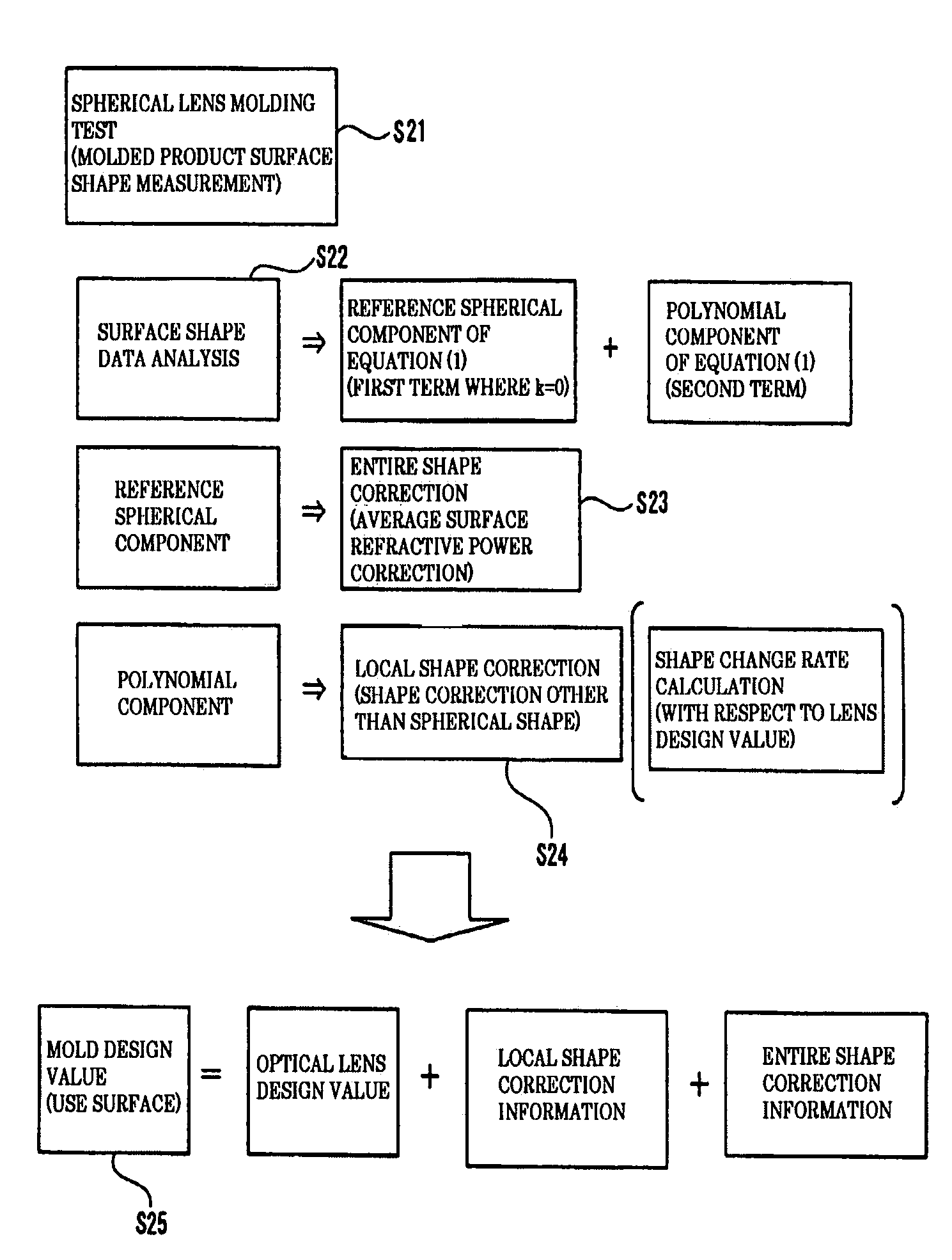
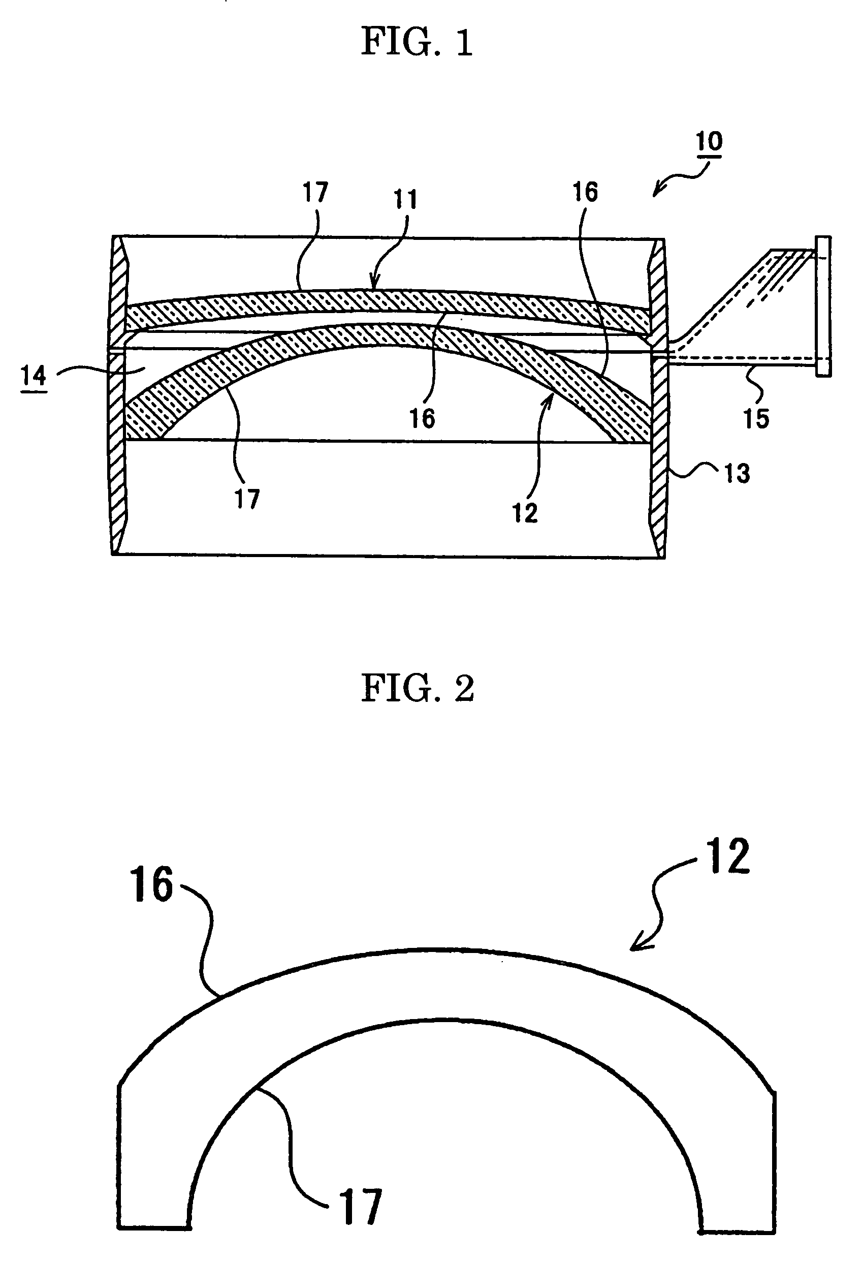
[0057]FIG. 1 is a sectional side view showing a mold having an upper mold and a lower mold which are produced by carrying out the first embodiment in a method for designing a mold according to the present invention. FIG. 5 is a graph showing a molded curved surface, a design curved surface and the like of an optical lens which is a molded product molded by tests from the mold in FIG. 1. FIG. 7 is a schematic diagram showing calculation or the like of entire shape correction information and local shape correction information in the design process of the upper mold and the lower mold in FIG. 1.

[0058](Explanation of Construction of Molding Mold for Producing Lens)

[0059]A mold 10 shown in FIG. 1 is for molding a plastic spherical lens by a manufacturing method called a cast method, and is constructed by including an upper mold 11, a lower mold 12 and a gasket 13. The above-described upper mold 11 and the lower mold 12 are collectively called...

second embodiment (fig.11 , fig.12)

[0138][B] Second Embodiment (FIG. 11, FIG. 12)

[0139](Explanation of Compiling Correction Information into Database)

[0140]FIG. 11 is a graph showing a shape change rate curve which is a part of the local shape correction information compiled into database that is used in a second embodiment in the method for designing a mold according to the present invention. FIG. 12 is a graph showing the entire shape correction information which is compiled into database that is used in the second embodiment in the method for designing the mold according to the present invention. In the second embodiment, the explanation of the same parts as in the aforementioned first embodiment will be omitted by using the same reference numerals and symbols, and the names.

[0141]The second embodiment differs from the aforementioned first embodiment in the following point. In FIG. 8, steps S31 to S40 are previously carried out for all kinds of molds. On this occasion, each correction information is compiled into ...

third embodiment

[0159][C] Third Embodiment

[0160](Explanation of Aspherial Shape Correcting Method by Spherical Correction Value)

[0161]The third embodiment is for correcting and designing design values of the use surfaces which are molding surfaces in the upper mold and the lower mold of the mold with which a molded product (optical lens) with the curved surface in the aspherical shape is molded by utilizing the correction information (the entire shape correction information, the shape change rate which is a part of the local shape correction information) which is compiled into database in the aforementioned second embodiment and for molding a molded product (optical lens) with the curved surface in a spherical shape.

[0162]The method for compiling the entire shape correction information for molding the optical lens with the curved surface in a spherical shape, and the shape change rate which is a part of the local shape correction information into database for each characteristic of the optical lens...


PUM

PropertyMeasurementUnit
outer diameteraaaaaaaaaa
diameteraaaaaaaaaa
diameteraaaaaaaaaa

Abstract

A mold with which a molded product in a desired shape with an aspherical curved surface is molded can be designed with high precision by correcting shape deformation of the molded product molded from the mold.A mold 10 in which use surfaces 16 of an upper mold 11 and a lower mold 12 are formed to be design curved surfaces of the optical lens in a spherical shape is prepared. A curved surface shape of the optical lens molded from the mold is measured, a measured value is approximated by an equation (1) which is an equation of an aspherical surface and a curved surface of the molded optical lens is specified as an aspherical surface. Information corresponding to an error between the curved surface of the optical lens specified by the equation of the aspherical surface and the above-described design curved surface is compiled into database for each of characteristics of the optical lens as correction information for molding the optical lens of which curved surface is in the spherical shape. By using the correction information compiled into database, design values of the use surfaces in the upper mold and the lower mold of the mold with which the optical lens of which curved surface in the aspherical shape is molded are corrected to design them.[Mathematical⁢⁢Expression⁢⁢10]Z=C⁢⁢ρ21+1-(1+K)⁢C2⁢ρ2+∑i=2n⁢A2⁢i⁢ρ2⁢i.(1)

Description

TECHNICAL FIELD[0001]The present invention relates to a mold designing method for designing a mold with which a molded product in a desired shape is molded by correcting a shape change of the molded product when molding the molded product (for example, an optical lens) from the mold, a mold designed by the mold designing method, and a molded product molded by the mold.BACKGROUND ART[0002]In molding an optical lens, when a mold is designed and produced by using designing values of the optical lens for the mold as they are, the optical lens produced with the mold sometimes is not produced in the same shape as that of the designing values. This is because of mold shrinkage being dependent on the material, stress due to the shape of the optical lens and the like, and because the mold surface of the mold is not transferred to the lens surface with high precision.[0003]For example, when molding is performed by using a mold having a spherical molding surface to mold a spherical lens, the m...

Claims


Application Information

Patent Timeline
Patent Type & Authority Patents(United States)
IPC IPC(8): G06F19/00G06F7/60B29C33/38B29C45/76B29D11/00B29L11/00G02B3/00G02C7/02
CPCB29C33/3835B29D11/00413B29D11/00538B29L2011/0016B29C33/38B29D11/00G02C7/02G02B3/00
Inventor UENO, YASUNORISATO, YOSHIYUKI
Owner HOYA CORP
Learn More