System for controlling valve timing of an engine with cylinder deactivation

a technology of valve timing and cylinder deactivation, which is applied in the direction of electrical control, machine/engine, electric control of exhaust, etc., can solve the problems of disadvantages of using the same variable cam timing value, and achieve the effects of improving overall system performance, low emissions, and efficient fuel usag

Inactive Publication Date: 2007-07-31
FORD GLOBAL TECH LLC
View PDF83 Cites 90 Cited by
  • Summary
  • Abstract
  • Description
  • Claims
  • Application Information

AI Technical Summary

Benefits of technology

[0008]Thus, by using different valve timing, and / or valve lift, for cylinders carrying out combustion from cylinders without fuel injection, it is possible to provide sufficient NOx reduction and fuel economy benefits to replace, or supplement, external exhaust gas recirculation. Furthermore, since each group of cylinder has an actuator, it is possible to alternate which cylinder group is deactivated, thereby providing even wear, without requiring two EGR valve systems.
[0009]The inventors herein have further recognized other disadvantages with prior variable cam timing approaches when applied in a system that disables fuel injection to cylinders. Specifically, disadvantages can be encountered when using the same variable cam timing value for cylinders that are operating without fuel injection as for cylinders that are carrying out combustion of injected fuel. Specifically, when transitioning from operating with some cylinders combusting and other pumping air (without injected fuel) to operation with all cylinders combusting, the valve conditions which provide the best combustion in the cylinders which had already been in operation can be different from the valve conditions which provide the best restarting combustion in the cylinders which were pumping air without injected fuel.
[0013]Thus, by providing the re-enabled cylinders with valve operation determined to provide accurate re-starting of combustion, more reliable cylinder reactivation can be achieved.
[0014]Finally, the inventor herein has recognized that in the case when one must use the same variable cam timing value for both groups of cylinders (in the case where a common actuator is used), the optimal actuator condition varies depending on whether both the groups are carrying out combustion, or whether one group is carrying out combustion and the other is inducting air with substantially no injected fuel. Further, as discussed above, the valve conditions which provide the best combustion in the cylinders which had already been in operation can be different from the valve conditions which provide the best restarting combustion in the cylinders which were pumping air without injected fuel.
[0018]An advantage of such operation is that overall system performance can be improved, since cylinder valve operation can be selected based on more than providing efficient fuel usage and low emissions for the combusting cylinders. For example, cylinder valve operation can also be selected taking into account the deactivated cylinders, such as pumping loss of deactivated cylinders not carrying out combustion. In other words, since the first and second group are governed by the same cylinder valve actuator (in one example, they would have the same cam timing, such as for a v-8 engine where at least some of the cylinders in the two groups are in a single bank), overall operation of the engine is improved.
[0019]In this way, it is possible, in one example, to adjust the steady state position for optimal fuel economy and emissions performance from the combined cylinder groups, since a single actuator is used for both groups. Further, in the case where there is a third and fourth group having a second actuator (such as in a V-8 engine), it is possible to alternate which cylinder group is deactivated, without requiring two EGR valves. As such, numerous advantages can be achieved.BRIEF

Problems solved by technology

The inventors herein have further recognized other disadvantages with prior variable cam timing approaches when applied in a system that disables fuel injection to cylinders.
Specifically, disadvantages can be encountered when using the same variable cam timing value for cylinders that are operating without fuel injection as for cylinders that are carrying out combustion of injected fuel.

Method used


Image

  • System for controlling valve timing of an engine with cylinder deactivation
  • System for controlling valve timing of an engine with cylinder deactivation
  • System for controlling valve timing of an engine with cylinder deactivation

Examples


Embodiment Construction

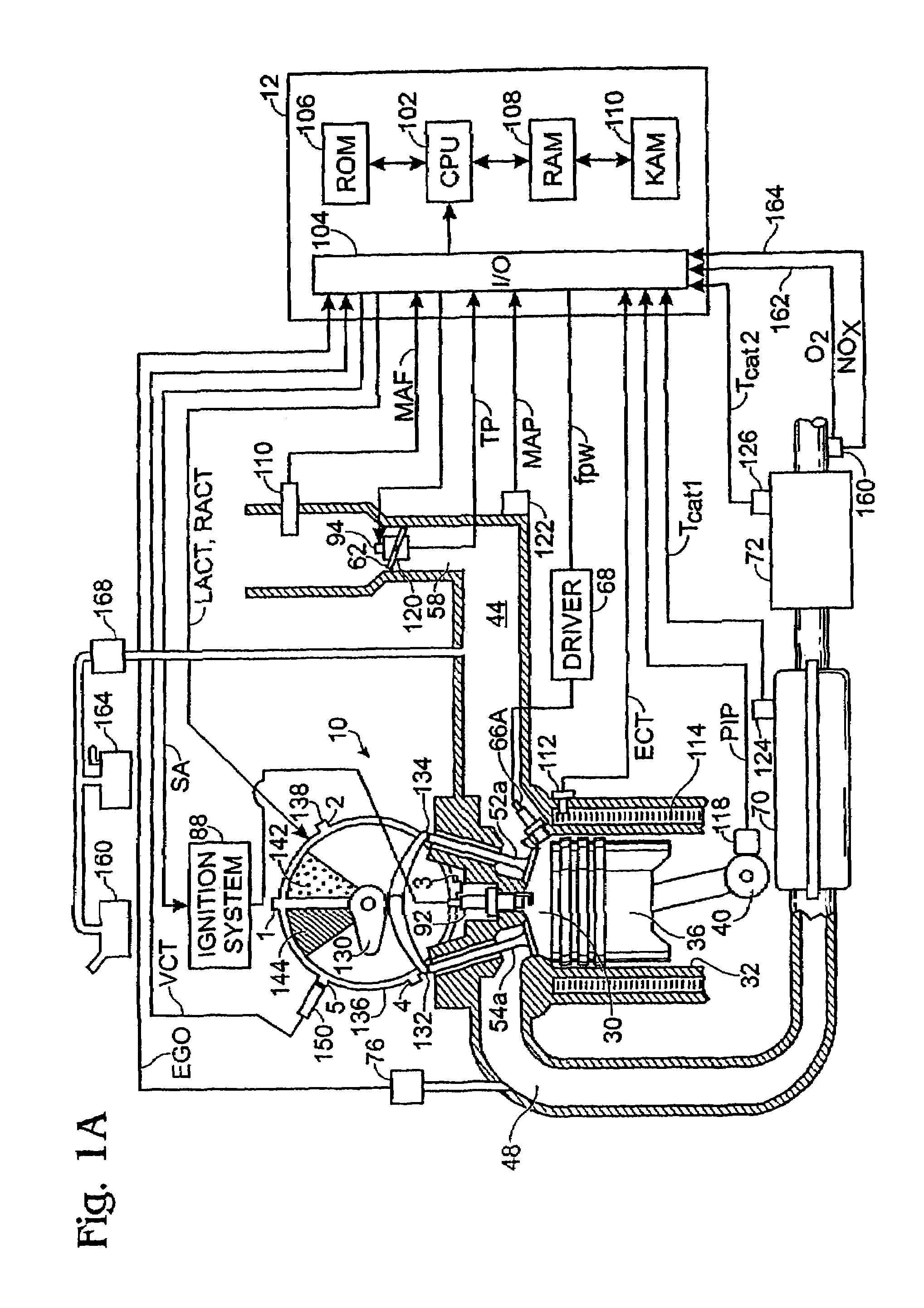
[0031]Referring to FIG. 1, internal combustion engine 10, further described herein with particular reference to FIGS. 1A and 1B, is shown coupled to torque converter 11 via crankshaft 13. Torque converter 11 is also coupled to transmission 15 via turbine shaft 17. Torque converter 11 has a bypass, or lock-up clutch 14 which can be engaged, disengaged, or partially engaged. When the clutch is either disengaged or partially engaged, the torque converter is said to be in an unlocked state. The lock-up clutch 14 can be actuated electrically, hydraulically, or electro-hydraulically, for example. The lock-up clutch 14 receives a control signal (not shown) from the controller, described in more detail below. The control signal may be a pulse width modulated signal to engage, partially engage, and disengage, the clutch based on engine, vehicle, and / or transmission operating conditions. Turbine shaft 17 is also known as transmission input shaft. Transmission 15 comprises an electronically co...


PUM


Abstract

Various systems and methods are disclosed for carrying out combustion in a fuel-cut operation in some or all of the engine cylinders of a vehicle. Further, various subsystems are considered, such as fuel vapor purging, air-fuel ratio control, engine torque control, catalyst design, and exhaust system design.

Description

CROSS-REFERENCE TO RELATED APPLICATIONS[0001]The present application is a continuation of U.S. patent application Ser. No. 10 / 794,503, filed Mar. 5, 2004 now abandoned, titled “System for Controlling Valve Timing of an Engine with Cylinder Deactivation,” the entire contents of which are incorporated herein by reference.[0002]The present application is also a continuation-in-part of U.S. patent application Ser. No. 10 / 844,822, filed May 12, 2004 now U.S. Pat. No. 7,047,932, titled “Method to Improve Fuel Economy in Lean Burn Engines with Variable-Displacement Like Characteristics”, which is a continuation of U.S. patent application Ser. No. 10 / 064,013, filed Jun. 4, 2002, now U.S. Pat. No. 6,758,185, the entire contents of which are incorporated herein by reference.BACKGROUND AND SUMMARY[0003]Engines are usually designed with the ability to deliver a peak output, although most engine operation is performed well below this peak value. As such, it can be beneficial to operate with some...

Claims


Application Information

Patent Timeline
Patent Type & Authority Patents(United States)
IPC IPC(8): F01N3/00F01L1/34F01L13/00F01N3/08F01N11/00F01N13/02F02D7/00F02D13/06F02D17/02F02D41/00F02D41/36F02M7/00F02M25/07F02M25/08
CPCF01L13/00F01N13/009F01N3/0807F01N3/0842F01N3/101F01N11/002F02D13/06F02D17/02F02D41/0032F02D41/0045F02D41/0087F02M25/0749F02M25/089F01N13/0093F01L13/0015F01L2800/08F02D41/187F02D2041/288Y02T10/47Y02T10/18Y02T10/22F02M26/43Y02T10/12Y02T10/40Y02A50/20
Inventor BIDNER, DAVIDSURNILLA, GOPICHANDRADOERING, JEFF
Owner FORD GLOBAL TECH LLC
Why Eureka
Try Eureka