Display control device and display device

a display device and control device technology, applied in the field of display control devices and display devices, can solve the problems of inability to realize the function by hardware, the display capabilities of recent display devices have not necessarily reached an adequate level, and cannot be realized by a simple operation circuit, etc., to suppress color clipping, suppress flickering in image displays, and achieve the effect of convenient realization

Active Publication Date: 2007-07-17
PANASONIC CORP
View PDF2 Cites 11 Cited by
  • Summary
  • Abstract
  • Description
  • Claims
  • Application Information

AI Technical Summary

Benefits of technology

[0015]Thus, an object of the present invention is to provide an image display control device which can be realized readily in terms of hardware, which can suppress flickering in image displays, and which can suppress color clipping.

Problems solved by technology

However, the display capabilities of recent display devices have not necessarily reached an adequate level, and therefore, measures are necessary for improving the apparent view-amenity better than the cases where input image signals are input as they are into a display device.
(Problem 1) Since the sigmoid function is nonlinear, it cannot be realized by a simple operational circuit.
It is therefore not practical in realizing the function by hardware.
However, in a case where pictures change in a continuous manner, this parameter tends to change greatly for every frame of picture and a flicker occurs in the displayed image after conversion.
Therefore, when a process of increasing the Y signal is performed without special consideration and then an inverse mapping from the Yuv color space to the RGB color space is performed, a result that exceeds the brightness component capacity of the RGB color space, that is, a result that cannot be displayed, actually may be obtained.
Consequently, color clipping may occur.
However, when the color after the process in the Yuv color space is inversely mapped to the RGB color space, the result of B>100%, which cannot be displayed, is obtained, thus causing color clipping.

Method used


Image

  • Display control device and display device
  • Display control device and display device
  • Display control device and display device

Examples


first embodiment

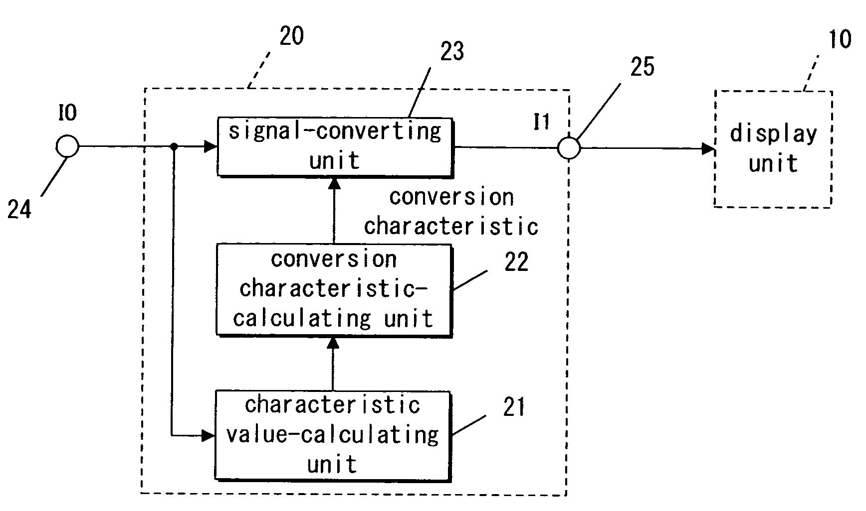
[0070]FIG. 1 through FIG. 3 concern a first embodiment. FIG. 1 is a block diagram of a display device according to the first embodiment of the present invention.

[0071]In FIG. 1, a display unit 10 is an LCD, CRT, etc., and any display unit may be used as long as it can perform display with the brightness component being provided with gradation.

[0072]A display control device 20 comprises an input terminal 24 and an output terminal 25, and controls the display state of the display unit 10 by means of an output image signal I1 from the output terminal 25.

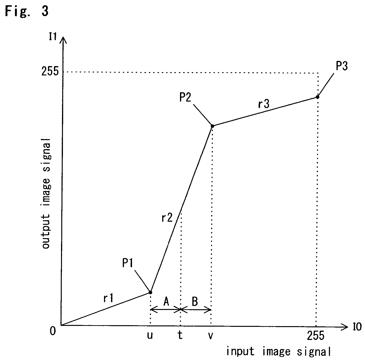
[0073]The display control device 20 comprises a characteristic value-calculating unit 21 that calculates a characteristic value for a frame of an image based on an input image signal I0 input from the input terminal 24. With the present embodiment, the input image signal I0 is of video signal components, which are brightness components in the present embodiment. Other arbitrary brightness components may be used as the brightness compone...

second embodiment

[0088]FIG. 4 and FIG. 5 concern a second embodiment. FIG. 4 is a block diagram of a display device according to the second embodiment of the present invention. The present embodiment is favorable for a case where a display unit 30 has a light source 32 and a display panel 31, which is illuminated by the light source 32 (typically, when the display unit 30 is a back-light type LCD).

[0089]A display control device 40 according to the second embodiment comprises a conversion characteristic-calculating unit 22 and a signal-converting unit 23 which are the same as those of the first embodiment. Also, a light source-adjusting device 45, which is placed at the subsequent stage of the display control device 40, has a first output terminal 43 connected to the display panel 31, and a second output terminal 44 connected to the light source 32.

[0090]With the present embodiment, in the light source-adjusting device 45, a multiplication unit 42 is placed between the signal-converting unit 23 and t...

first modification example

[0097]FIG. 13 and FIG. 14 concern a First Modification Example of the second embodiment. As shown in FIG. 13, with this First Modification Example, in place of the light source-adjusting device 45 of the second embodiment (see FIG. 4), a light source-adjusting unit 28 is placed between the display control device 40 and the display unit 30.

[0098]The light source-adjusting unit 28 adjusts, on the basis of an output image signal I1 of the signal-converting unit 23, an output image signal I2 to be outputted to the display panel 31 and a light emission control signal P to be outputted to the light source 32 in a correlated manner. Unlike the structure of FIG. 4, with the present example, the characteristic value-calculating unit 41 is not required to determine the factor K and the light emission control signal P.

[0099]The light source-adjusting unit 28 performs the following process. That is, the light source-adjusting unit 28 inputs the output image signal I1 for a single frame from the...


PUM


Abstract

A display control device is provided which includes characteristic value-calculating unit for calculating a characteristic value based on an input image signal, a conversion characteristic-calculating unit for determining a conversion characteristic from the characteristic value, and a signal-converting unit for converting the input image signals in accordance with the determined conversion characteristic. The conversion characteristic has a low level region segment, which is close to the origin of axes respectively representing the input image signal and an output image signal of the display control device, a high level region segment, which is close to a full scale point, and a middle level region segment, which is positioned between the low level region and high level region, and the slope in the middle level region is set so as to be larger than both of the slopes of the low level region and the high level region.

Description

BACKGROUND OF THE INVENTION[0001]1. Field of the Invention[0002]The present invention concerns an image display control device operable to provide improved feeling contrast for input image signals, and a display device utilizing the image display control device.[0003]2. Description of the Related Art[0004]With the development of the information society, occasions in which users view images that are displayed on display devices are increasing. However, the display capabilities of recent display devices have not necessarily reached an adequate level, and therefore, measures are necessary for improving the apparent view-amenity better than the cases where input image signals are input as they are into a display device.[0005]In regard to this, a reference 1 (“Gradation Conversion by a Sigmoid Function in a Digital Camera System,” Watanabe et al., Japan Hardcopy 2000 Collected Papers B-27, The Imaging Society of Japan) proposes a method of using a sigmoid function to make black (low leve...

Claims


Application Information

Patent Timeline
Patent Type & Authority Patents(United States)
IPC IPC(8): G09G5/00H04N5/20H04N9/64
CPCH04N5/20H04N9/646
Inventor KIUCHI, SHINYAIKEDA, JUNOJIMA, SHUICHIHIRASHIMA, TSUYOSHIHATA, RYOUTA
Owner PANASONIC CORP
Why Eureka
Try Eureka