
Laser wavelength control arrangement and method

a technology of laser wavelength and control arrangement, which is applied in the direction of semiconductor lasers, laser details, electrical equipment, etc., can solve the problems of difficult control and stabilization of wavelength and power of lasers, no one of these techniques is applicable to all specifics, and the high power transmission of such a narrow linewidth laser is severely hampered, etc., to achieve accurate wavelength control, the effect of low cos

Inactive Publication Date: 2007-07-10
WSOU INVESTMENTS LLC +1
View PDF5 Cites 0 Cited by
  • Summary
  • Abstract
  • Description
  • Claims
  • Application Information

AI Technical Summary

Benefits of technology

This approach provides practical, inexpensive, and accurate wavelength control across a wide range of laser applications, including low output power scenarios, effectively stabilizing the laser's operating wavelength and power, reducing noise and interference, and maintaining performance over the life of the device.

Problems solved by technology

Control and stabilization of the wavelength and power of the laser becomes even more difficult when the target values for these parameters are expected to assume one of a multiplicity of values in wide respective ranges.
No one of these techniques is applicable to all the specific situations that can occur in a transmission system.
High power transmission for such a narrow linewidth laser is severely hampered because the stimulated Brillouin scattering (SBS) threshold limits the power spectral density that can be transmitted by an optical fiber before SBS deteriorates signal transmission in the fiber.
But this technique is inapplicable to pump lasers used for Raman amplification because it would have the deleterious effect of amplitude modulating the gain in direct response to the dithering applied to the pump laser.
Lasers stabilized by the use of fiber Bragg gratings exhibit a high relative intensity noise (RIN) which limits the suitability of such stabilized lasers as a co-propagating pump lasers in Raman amplification applications.
In addition, proper operation of the fiber Bragg grating stabilization technique requires a relatively high laser output power.
Wavelength lockers are relatively expensive and decrease the available power budget because of insertion and device losses.
These devices, especially state of the art devices, are only operable with single mode lasers.
But lasers that are used as pump lasers in optical amplifier applications tend not to be single mode lasers.
Moreover, wavelength locked lasers are operable over a very limited output power range.
Injection current changes cause a concomitant detuning in the operating wavelength of the laser, which can be sufficiently large to cause interference in the adjacent WDM channels.
None of the techniques known in the prior art provide for practical, inexpensive, and accurate wavelength stabilization and control in a wide range of laser applications and for a broad range of laser output powers, especially where that range includes low output power.

Method used


Image

  • Laser wavelength control arrangement and method
  • Laser wavelength control arrangement and method
  • Laser wavelength control arrangement and method

Examples


Embodiment Construction

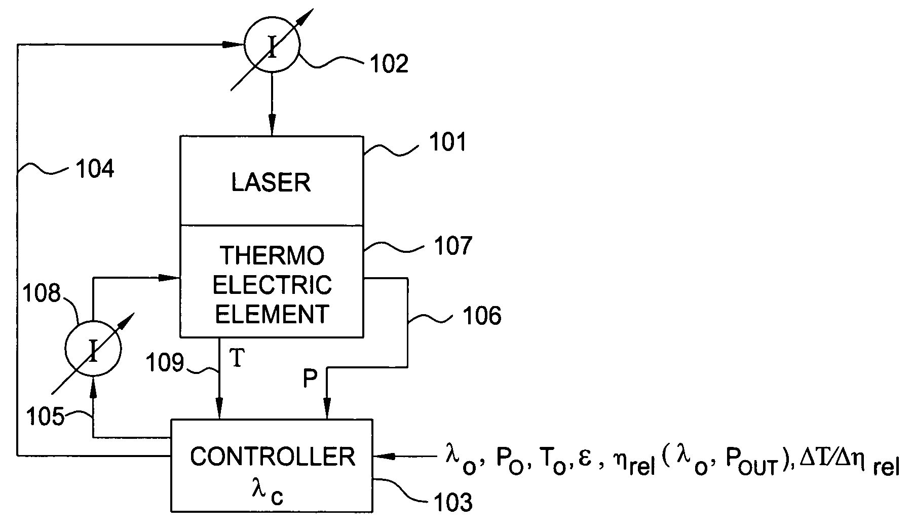
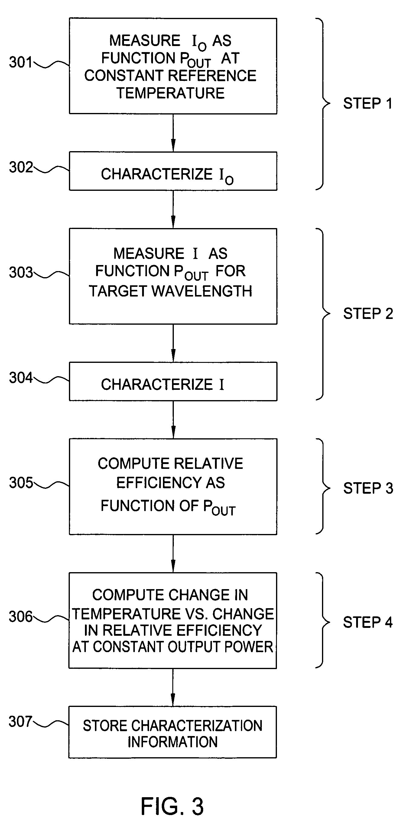
[0022]The following terms and variables used within this description are provided below for ease of reference:[0023]Pout=laser output power;[0024]P0=target laser output power;[0025]I=laser injection current;[0026]I0=reference laser injection current;[0027]λc=laser wavelength;[0028]λ0=target wavelength;[0029]ηrel=relative efficiency;[0030]Δηrel=relative efficiency change;[0031]ΔT=temperature change;[0032]ε=wavelength adjustment threshold value;[0033]t=time; and[0034]t0=reference time.

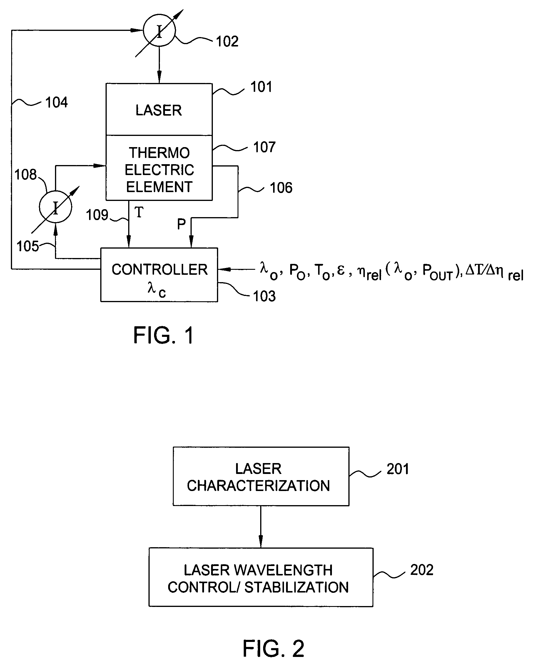
[0035]A typical operating environment for practicing the present invention is shown in a simplified block diagram in FIG. 1. A laser 101 driven by a controllable injection current source 102 is monitored, measured, stabilized, and controlled to operate at a desired target operating wavelength and output power by a controller 103. Controller 103 supplies appropriate control signals both to the controllable current source 102 that supplies the laser injection current on lead 104 and to the controllable cur...


PUM


Abstract

Wavelength control and stabilization of a laser is achieved by a practical, inexpensive, and accurate technique adapted for most optical transmission system applications by a method involving a laser characterization phase and a laser wavelength control and stabilization phase. This technique is applicable to both single mode lasers and multimode lasers. It is especially useful in those applications where the desired laser output power can vary over a wide range, including relatively low power above the lasing threshold.

Description

BACKGROUND OF THE INVENTION[0001]1. Field of the Invention[0002]This invention relates to a method and apparatus for controlling and stabilizing the operating wavelength of a laser operating at different output power levels and, more particularly, for controlling and stabilizing the operating wavelength for a semiconductor laser.[0003]2. Description of the Related Art[0004]Optical transmission systems rely heavily on the use of lasers in the transmission network. Optical signals output by lasers are modulated directly or by external modulation to carry information and control signals in optical networks. As the information signals traverse the optical network, they are amplified by Raman techniques or by discrete amplification techniques that rely on pump lasers to stimulate the amplification process. In all these applications, control of laser operating parameters such as output power and operating wavelength is necessary. As the lasers age or undergo environmental changes such as ...

Claims


Application Information

Patent Timeline
Patent Type & Authority Patents(United States)
IPC IPC(8): H01S3/13
CPCH01S5/06804H01S5/0687H01S5/0617
Inventor BOLLENZ, BERNDCZOTSCHER, KONRADWERNER, DIETER
Owner WSOU INVESTMENTS LLC
Learn More