
Fuel cell manifold cable end clamp

a technology of manifolds and end clamps, which is applied in the direction of fuel cells, cell components, fuel cell groupings, etc., can solve the problems of high volume of fuel cell power plants, high volume of manifolds, and the size of manifolds, and achieves no volume increase, easy assembly, and low volume

Active Publication Date: 2007-07-10
AUDI AG
View PDF4 Cites 2 Cited by
  • Summary
  • Abstract
  • Description
  • Claims
  • Application Information

AI Technical Summary

Benefits of technology

The solution effectively prevents manifold leaks by applying adjustable clamping force without adding volume or complexity, allowing easy assembly and retrofitting, while ensuring electrical insulation and minimal machining requirements.

Problems solved by technology

In motor vehicle applications, the volume of the fuel cell power plant is severely limited so that the size of the manifolds as well as any corrective equipment, such as clamps, is highly restricted.

Method used


Image

  • Fuel cell manifold cable end clamp
  • Fuel cell manifold cable end clamp
  • Fuel cell manifold cable end clamp

Examples


Embodiment Construction

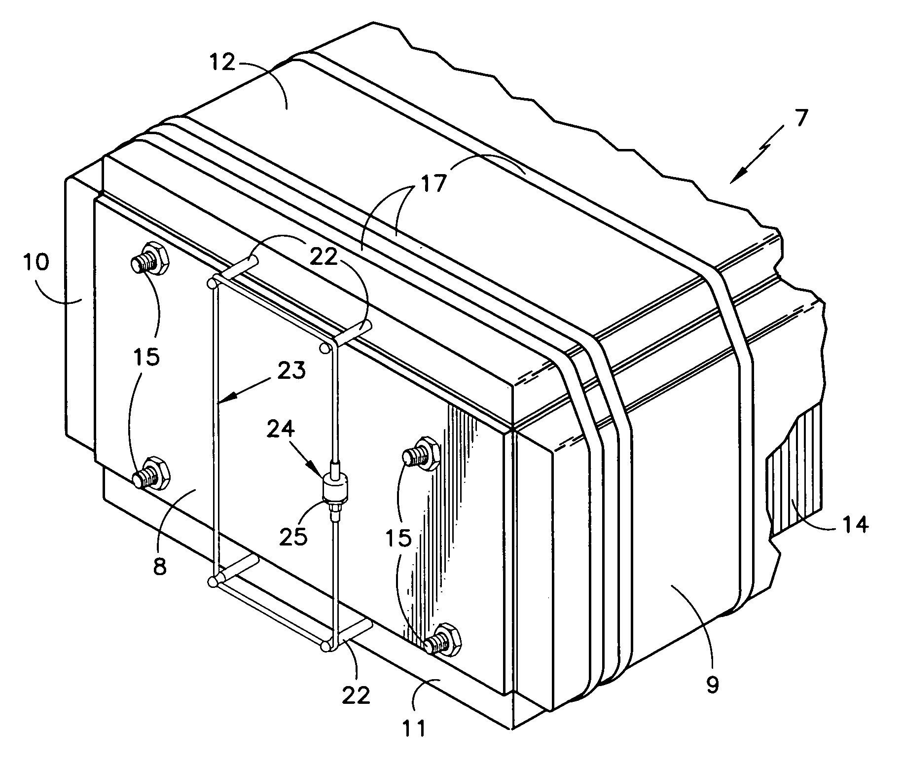
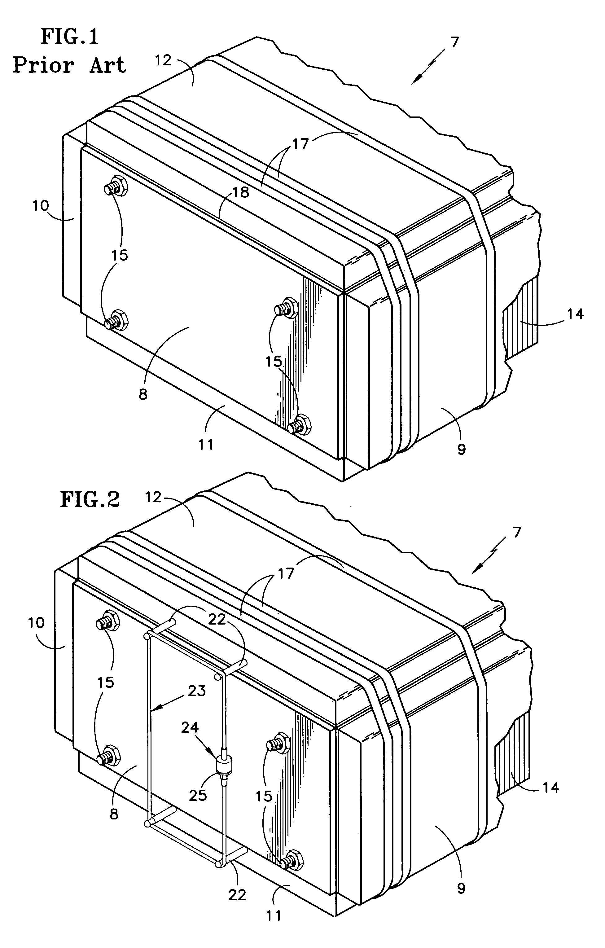
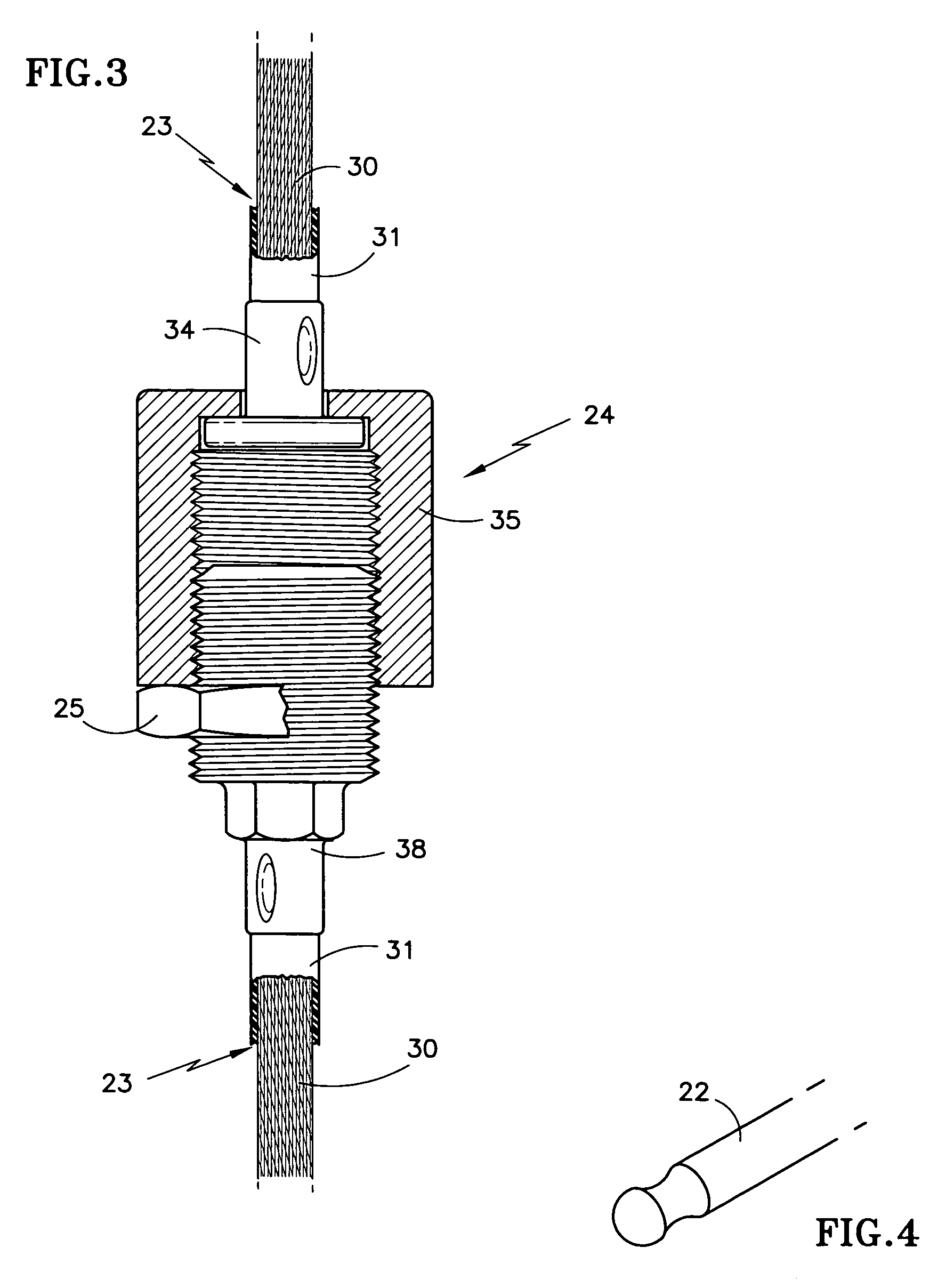
[0012]Referring to FIG. 2, four grooved pins 22 are bonded into holes provided in the ends of the manifolds 11, 12, there being a cable 23 wrapped around the pins 22 and closing upon itself at a turnbuckle 24 which has a locknut 25.

[0013]If desired, and proper spacing and clearance can be provided without interference with other apparatus on the pressure plates 8, the invention may be practiced utilizing a single pin 22 extending outwardly from the end of each related manifold.

[0014]One of the advantages of the present invention is that the pins can be located wherever there is room for them and the cable without interfering with other parts of the fuel cell stack. In fact the pins on one end do not have to be symmetrically aligned with the pins on the other end of the stack. The pins may be closer together on one end of the stack than they are on the other end of the stack. If desired, and if there is clearance near the center of the stack, only a single set of pins may be utilized...


PUM

PropertyMeasurementUnit
pressureaaaaaaaaaa
tensionaaaaaaaaaa
volumeaaaaaaaaaa

Abstract

A pair of reactant gas manifolds (11 and 12) on opposite sides of a fuel cell stack (7) are sealed to the fuel cells (14) and pressure plates (8) by means of pressure applied by load cables (17). The centers of the manifolds are prevented from having leakage between them and the end plates by means of a tensioning system comprising a plurality of pins (22) extending outwardly from the ends of the manifolds, and tensioning cables (23) extending around the pins in a closed loop and tensioned by a turnbuckle (24).

Description

TECHNICAL FIELD[0001]This invention relates to clamping the ends of fuel cell reactant manifolds by drawing two manifolds towards each other on opposite sides of the fuel cell stack, by means of a tensioning cable wrapped around pins.BACKGROUND ART[0002]A fuel cell stack, part of a fuel cell power plant known to the prior art is illustrated in FIG. 1. In FIG. 1, the fuel cell stack 7 includes a pressure or end plate 8, a fuel inlet / outlet manifold 9, a fuel turn manifold 10, and air / coolant inlet / outlet manifold 11 and an air turn manifold 12. The manifolds 9–12 are sealed to the edges of the fuel cells 14 and the edges of the pressure plate 8 by means of foam gaskets, silicone rubber, and possibly other components, examples of which are shown in copending U.S. patent application Ser. No. 10 / 619,406, filed Jul. 15, 2003. The pressure plates are drawn together by tie rods 15, as is known. The manifolds are pressed to the stack by load cables 17. The air / coolant manifolds experience l...

Claims


Application Information

Patent Timeline
Patent Type & Authority Patents(United States)
IPC IPC(8): H01M8/24H01M2/08
CPCH01M8/247H01M8/248Y02E60/50
Inventor PETTY, DALE W.PHILLIPS, CYNTHIA M.
Owner AUDI AG
Learn More