
Bicycle rear suspension

a rear suspension and bicycle technology, applied in the field of bicycles, can solve the problems of compromising lateral rigidity of the linkage, weight and cost penalties, complicated incorporation, etc., and achieves the effect of enhancing the lateral stiffness of the suspension, enhancing the overall stiffness of the linkage, and high commonality of pivot components

Inactive Publication Date: 2007-07-10
ATB SALES
View PDF8 Cites 12 Cited by
  • Summary
  • Abstract
  • Description
  • Claims
  • Application Information

AI Technical Summary

Benefits of technology

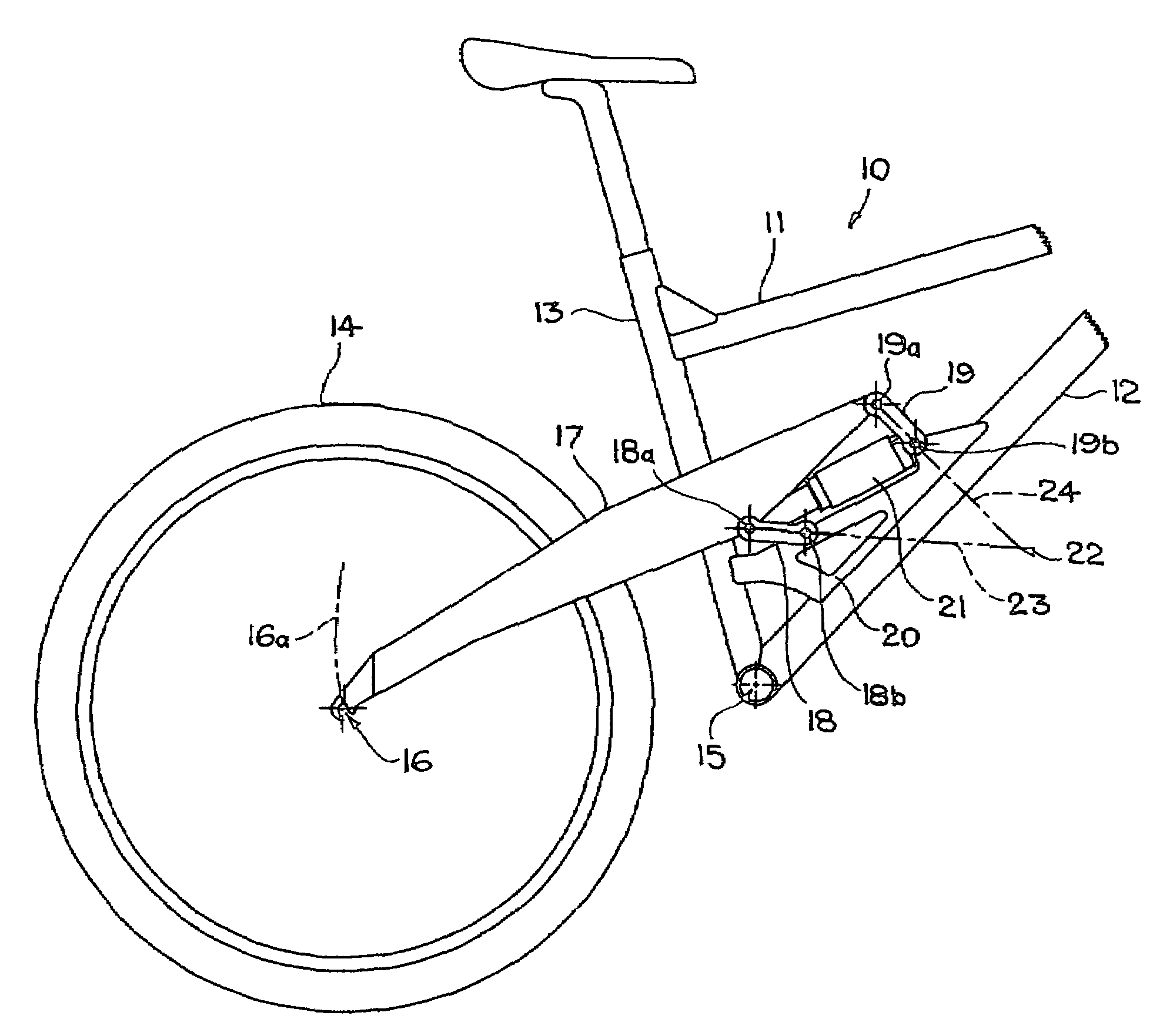
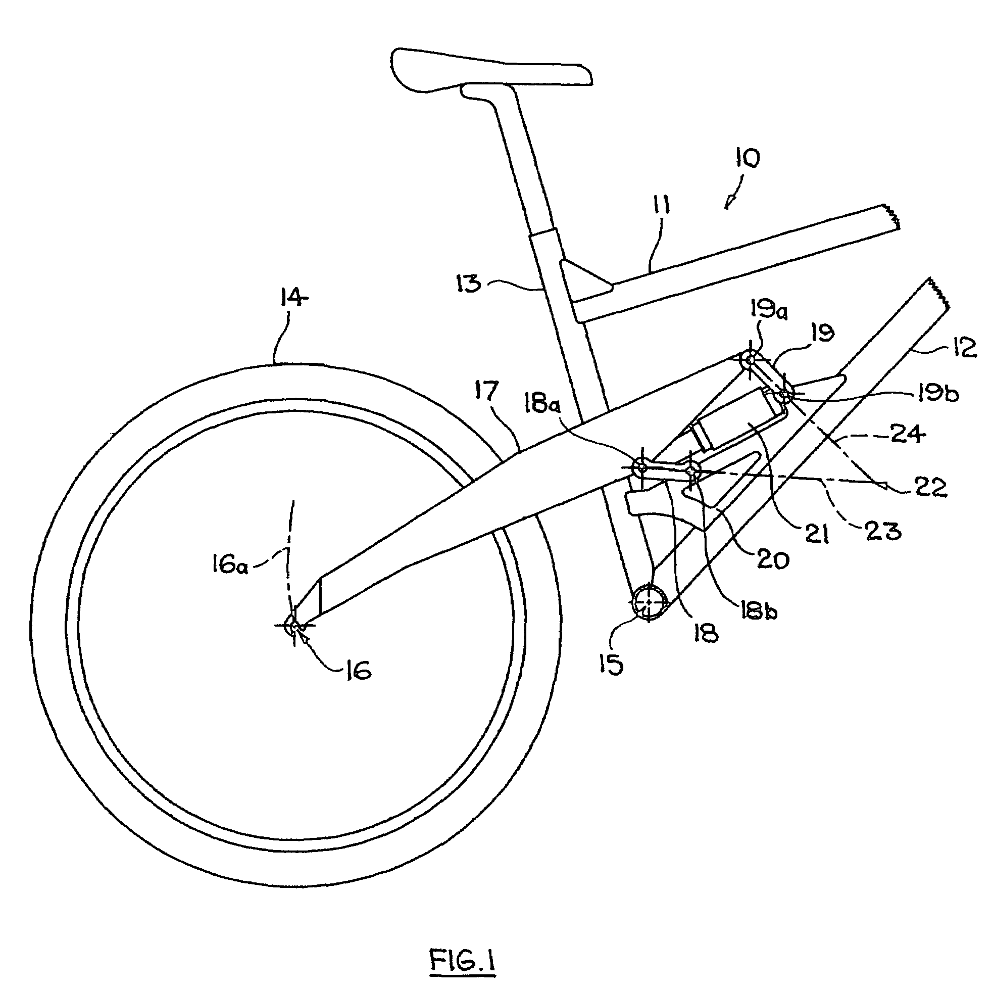
[0010]In the case of a bicycle embodying the present invention, pivot points for the spring and damper unit and the elements of the linkage are shared, with the result that only four pivot points are required. This produces savings in weight and cost with respect to pivot point components, but because one link is disposed forwardly of the other link, i.e. the links do not overlap in the fore and aft direction of the bicycle, the four pivot points of the links are spaced apart in that direction and the rear suspension does not suffer any reduction in its capability to resist lateral deflection of the wheel. Adaptation of the frame structure is not necessary, in particular it is possible to use a conventional frame triangle with a straight, uninterrupted seat tube. The spring and damper unit is, moreover, accommodated within the space enclosed by the elements of the linkage, which provides a compact layout without intrusion of the unit into areas where it might represent an obstruction.
[0012]Each of the pivot points preferably comprises a single continuous pivot pin, which can pass through bearing bores in—as the case may be—the arm, links, frame and spring and damper unit. A high level of commonality of pivot components can be achieved, particularly if the pivot pins are substantially identical and, for example, associated with identical plain, ball or roller bearings. In addition, the links themselves can be substantially identical, in each instance preferably consisting of two substantially parallel arms. The parallel arms enhance lateral stiffness of the suspension and accommodate the spring and damper unit therebetween, so as to allow a symmetrical arrangement in which the unit is in a central position.
[0013]For preference, the links and the spring and damper unit are disposed substantially in a space partly or fully enclosed by the frame. Such a space can be, for example, a recess in a monocoque frame or, if the frame comprises a down tube and a seat tube, a region between the tubes. Location of the links and the spring and damper unit within such a space, for example an angular region between the down and seat tubes, provides a degree of protection of these components and the associated pivot pins and bearings from direct exposure to mud splash from the wheels. In addition, location of the links and unit in the mentioned space and thus above the chain wheel and pedal cranks normally mounted at a junction of the seat tube and down tube allows space for use of relatively wide links, which increases overall stiffness of the linkage.
[0014]With advantage, the pivot points at the frame are disposed on a bridge member extending between the down and seat tubes. Such a bridge member, apart from providing a simple and convenient mounting location for the frame pivot points, makes a significant contribution to the stiffness of the frame, notably in an area which is highly loaded.
[0015]It can also be of advantage for the rear suspension to have a capability of adjustment to vary the ride height of the bicycle to more readily cope with different degrees of terrain roughness and differing rider weights. For this purpose, the particular link pivot point, which is not shared with the spring and damper unit, at the frame is preferably adjustable in an arc about the frame pivot point of the other link. The arcuate adjustment can be achieved by sliding engagement of a pivot pin of the pivot point within a slot and fixing the pin in a selected position in the slot. By contrast, in the case of known rear suspensions with four-bar linkage it may be necessary to provide two such adjustment slots respectively for a link pivot point and a separate spring and damper unit pivot point.
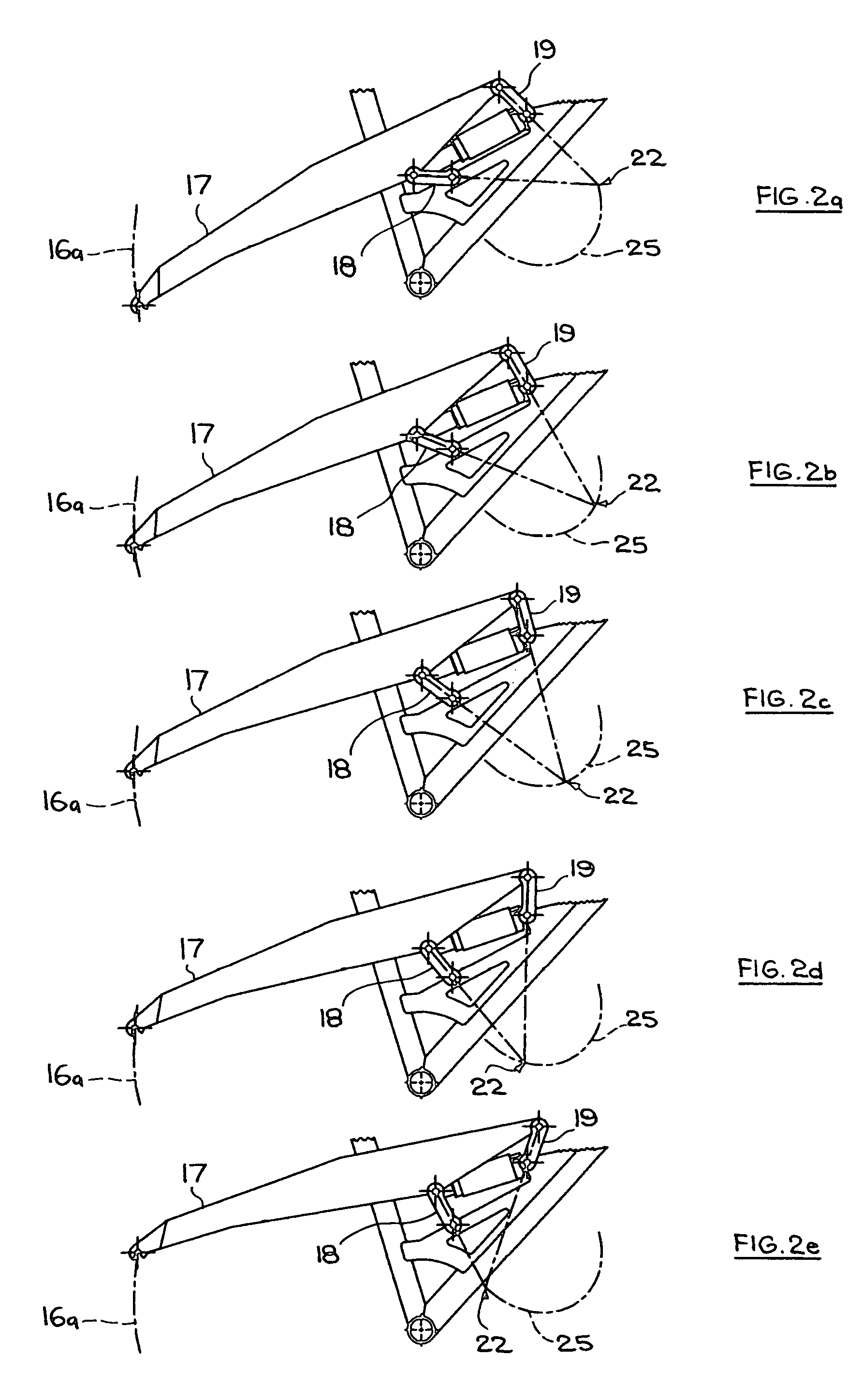
[0018]Preferably, the locus of the axis of the rear wheel during movement of the linkage from the end setting in the unloaded state to the end setting in the loaded state has the form of a curve with a radius which is greater in the latter end setting than in the former end setting. This particular locus has the effect of inducing chain growth relatively rapidly in an initial phase of upward travel of the rear wheel.

Problems solved by technology

Such units function satisfactorily, but can, on occasions, be complicated to incorporate in a bicycle, sometimes to the extent of necessitating adaptation of the frame structure to accommodate the unit and its mountings.
Weight and cost penalties result from the multiplicity of mountings for the unit and the various elements of the suspension linkage.
However, in the illustrated constructions the two links overlap in vertical direction entirely in the case of FIG. 3 and almost entirely in FIG. 2, with the consequence that the lateral rigidity of the linkage is compromised.
Two nearly vertical lines of flexure run through, respectively, the forward pivot points of the links and the rearward pivot points of the links so that, with the additional load imposed by the shared coupling of the spring and damper unit, the rear suspension has only a limited capability of providing resistance to forces tending to deflect the rear wheel laterally relative to the frame.
The solutions offered by DE 44 35 482 are therefore at the expense of the capability of the rear suspension to withstand critical deflections that can readily upset the tracking and poise of the bicycle.

Method used


Image

  • Bicycle rear suspension
  • Bicycle rear suspension
  • Bicycle rear suspension

Examples


Embodiment Construction

[0022]Referring now to the drawings there is shown part of a bicycle, for example a bicycle intended for off-road use (“mountain” bicycle), comprising a frame 10 with a crossbar 11, down tube 12 and seat tube 13. The crossbar 11 and down tube 12 may be united into a single component to the right of FIG. 1 and, whether so united or remaining separate, are connected to a steering assembly and front wheel forks or suspension (not shown) of the bicycle. At the junction of the down tube 12 and seat tube 13 there is provided a bearing location for a pedal crank drive fixedly connected with a drive sprocket of a chain-and-sprocket drive transmission (not shown) to a rear wheel 14 of the bicycle. A driven sprocket of the transmission is fixedly connected with an axle of the rear wheel and drive is transmitted from the drive sprocket to the driven sprocket by way of an endless chain. In the case of a drive transmission provided with gearing, several coaxial drive or driven sprockets of respe...


PUM


Abstract

A bicycle comprises a frame, a rear wheel and a rear suspension which comprises a swing arm carrying the wheel and two pivot links pivotably connected at respective pivot points with the frame and at respective pivot points with the arm so as to form, together with parts of the frame and arm, a four-bar linkage. The suspension further comprises a spring and damper unit pivotably connected with the frame at the pivot point of one link and with the arm at the pivot point of the other link so as to extend diagonally of the linkage and provide springing and damping of the suspension travel. The shared use of the link pivot points by the spring and damper unit serves to reduce construction and assembly costs as well as weight. One link is disposed forwardly of the other link with respect to the fore and aft direction of the bicycle so as to ensure lateral rigidity of the rear suspension.

Description

FIELD OF THE INVENTION[0001]The present invention relates to a bicycle and has particular reference to a rear wheel suspension in a bicycle.BACKGROUND OF THE INVENTION[0002]Bicycles intended for off-road and other rough terrain uses commonly have rear suspensions permitting sprung movement of the rear wheel relative to the bicycle frame. Suspensions of this kind have been developed to the level of multi-link systems, particularly four-bar linkages in which a rearwardly extending swing arm carrying the rear wheel is connected to a seat tube and / or down tube of the bicycle frame by way of pivot links. The swing arm, links and part of the tube or tubes form the elements of the linkage. The linkage geometry can be such as to not only provide effective wheel travel in response to the loads imposed by travel over uneven ground, but also to counteract a cyclic up-and-down motion or ‘bobbing’ effect of the rear suspension which otherwise arises as a reaction to and synchronous with the peri...

Claims


Application Information

Patent Timeline
Patent Type & Authority Patents(United States)
IPC IPC(8): B62K25/20B62K25/28
CPCB62K25/286
Inventor WHYTE, JON FRANK ROSS
Owner ATB SALES
Learn More