Hybrid vehicle
a hybrid vehicle and hybrid technology, applied in the field of hybrid vehicles, can solve the problems of reduced minimum ground clearance, insufficient driving force of the rear wheels, and unavoidable enlargement of the motor, and achieve the effect of increasing the power generation capability of the vehicl
- Summary
- Abstract
- Description
- Claims
- Application Information
AI Technical Summary
Benefits of technology
Problems solved by technology
Method used
Image
Examples
first embodiment
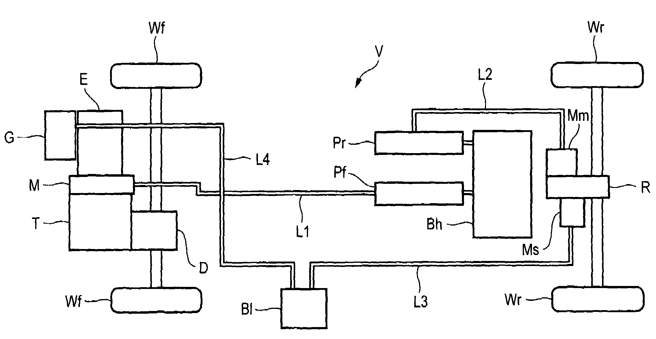
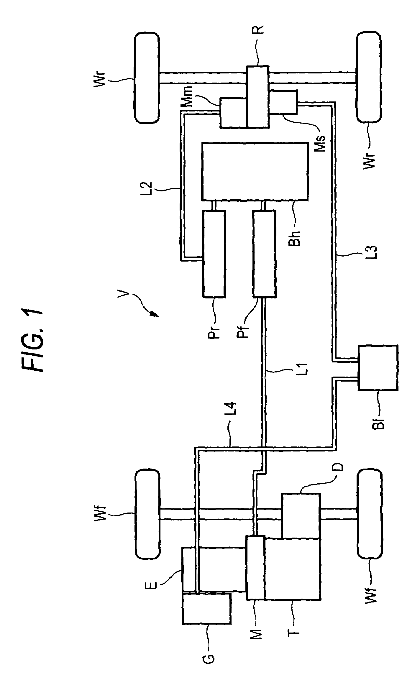
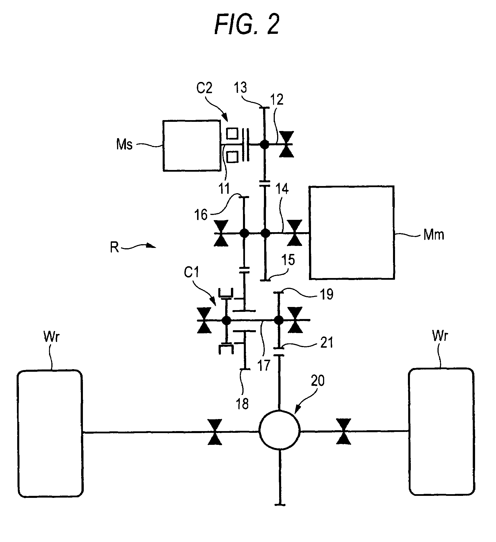
[0036]FIGS. 1 to 5 show the invention. FIG. 1 is a diagram showing an overall configuration of a hybrid vehicle. FIG. 2 is a diagram showing the construction of a driving system for rear wheels. FIG. 3 is a diagram showing a control system of motors. FIG. 4 is a graph showing changes in driving torques of main and sub rear motors relative to the vehicle speed. FIG. 5 is a graph showing changes in rotational speeds of the main and sub rear motors relative to the vehicle speed.
[0037]As shown in FIG. 1, a hybrid vehicle V has left and right front wheels Wf, Wf which are main driving wheels and left and right rear wheels Wr, Wr which are sub driving wheels. Among an engine E for driving the front wheels Wf, Wf, a transmission T and a differential D, a front motor M constituted by a three-phase alternating-current motor is interposed in line between the engine E and the transmission T. By driving the front motor M, the engine E is assisted in providing driving force, and by making the fr...
second embodiment
[0064]Next, the invention will be described by reference to FIG. 6.
[0065]In the first embodiment illustrated in FIG. 1, while the low-voltage battery B1 is interposed between the generator G driven by the engine E and the sub rear motor Ms, in the second embodiment, with the low-voltage battery Bl being removed, the generator G and the sub rear motor Ms is direct connected to each other via a direct-current wire L5. Consequently, the control of the driving torque of the sub rear motor Ms is implemented by controlling the generate output of the generator G driven by the engine E. According to this embodiment, the cost and space can be saved by removal of the low-voltage battery Bl.
third embodiment
[0066]Next, a third embodiment will be described by reference to FIG. 7.
[0067]In the first and second embodiments illustrated in FIGS. 1 to 6, while the power used to drive the sub rear motor Ms is supplied from the generated output of the generator G driven by the engine E, in the third embodiment, the generator G and the low-voltage battery B1 are removed, and instead, the high-voltage battery Bh and the sub rear motor Ms is connected to each other via a direct-current wire L6, a downverter 32, and a direct-current wire L7. The sub rear motor Ms is driven by lowering the voltage of the high-voltage battery Bh by the downverter 32. According to this embodiment, the cost and space can be saved by removal of the low-voltage battery B1 and the generator G.
PUM
 Abstract
Description
Claims
Application Information
 - R&D
- Intellectual Property
- Life Sciences
- Materials
- Tech Scout
- Unparalleled Data Quality
- Higher Quality Content
- 60% Fewer Hallucinations
Browse by: Latest US Patents, China's latest patents, Technical Efficacy Thesaurus, Application Domain, Technology Topic, Popular Technical Reports.
© 2025 PatSnap. All rights reserved.Legal|Privacy policy|Modern Slavery Act Transparency Statement|Sitemap|About US| Contact US: help@patsnap.com


