Knock-on sweep structure and tools therefor

a technology of retaining structure and knock-on sweep, which is applied in the field of tillage tools, can solve the problems of affecting the operation the failure of the retaining device to be replaced, etc., and achieves the effect of improving the retaining structure of the retaining device, simple and inexpensive manufacturing and assembly, and reliably holding the retaining devi

Inactive Publication Date: 2007-07-10
DEERE & CO
View PDF10 Cites 3 Cited by
  • Summary
  • Abstract
  • Description
  • Claims
  • Application Information

AI Technical Summary

Benefits of technology

[0005]It is therefore an object of the present invention to provide an improved sweep retaining structure for a knock-on sweep that overcomes most or all of the above-mentioned problems. It is another object to provide such an improved sweep retaining structure which is simple and inexpensive to manufacture and assemble and yet reliably holds the sweep on the shank and facilitates quick and easy removal of the sweep. Further objects include providing an improved sweep and providing an improved retainer for use with such structure.
[0006]It is yet another object to provide an improved sweep retaining structure which provides reliable retention independently of manufacturing tolerances, forces applied during sweep mounting and precise alignment of mating portions of the sweep assembly. It is another object to provide such a structure having an improved and simplified retainer mounting arrangement. It is a further object to provide such a structure wherein the retainer is positioned for proper engagement with a contact area on the sweep without direct contact with a bolt or similar fastener. It is still another object to provide such a structure having support and guidance structure for the detent to facilitate alignment and prevent bending of the detent.
[0007]It is yet another object to provide an improved sweep retaining structure which eliminates need for flat retaining clips and which provides improved wear and retaining characteristics compared to at least most previously available clip type retaining structures. It is another object to provide such a sweep retaining structure with integral retainer guide and wear reducing structure for improving retention and preventing retainer deformation.

Problems solved by technology

When the tool in such an assembly has to be replaced because of wear or damage, the bolts must be removed.
Wear and corrosion of the bolts substantially hinders removal and often makes the replacement a difficult and time-consuming task.
However, most retaining devices have suffered from one or more problems, including need for additional parts and the loss of sweeps when encountering high removal forces during transport and during rebounding of the shank from a tripped position.
Such detents generally help retain the sweeps on the shanks, but the forces exerted on a sweep, particularly forces exerted on deep tillage tools, can be so great that the sweep fails to stay on the shank.
The geometry of most previously available sweep detent arrangements, including non-symmetrical mating surfaces on some, usually limits penetration of the retaining surface into the hole so that retaining forces are limited.
Some care must be taken to align the protrusion with the hole, and part tolerances, variations in force used to mount the sweep, or lack of indexing of the clip relative to the shank can make such alignment troublesome.
A relatively small, ramped contact area between the clip and the hole also increases the potential for losing a sweep.
Soil moving up and around the stem portion of the sweep can move the clip from the detent position or wear away the clip until it is ineffective for holding the sweep on the shank.
Extreme forces on the detent, such as those which occur during rebound, can also cause deformation of the detent.
If the detent deforms, loosened sweeps can unacceptably dangle from the shank or be lost.

Method used


Image

  • Knock-on sweep structure and tools therefor
  • Knock-on sweep structure and tools therefor
  • Knock-on sweep structure and tools therefor

Examples


Embodiment Construction

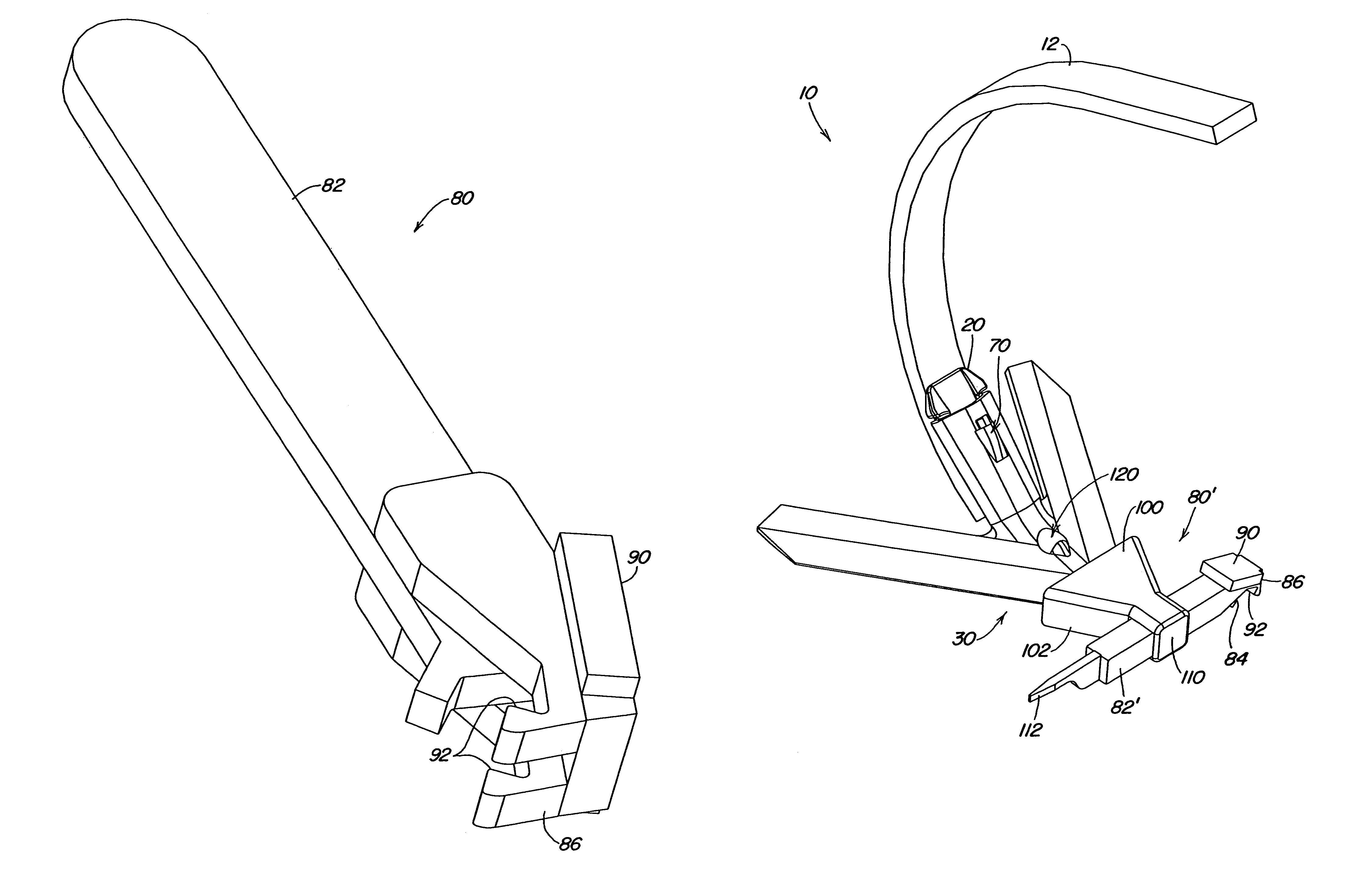
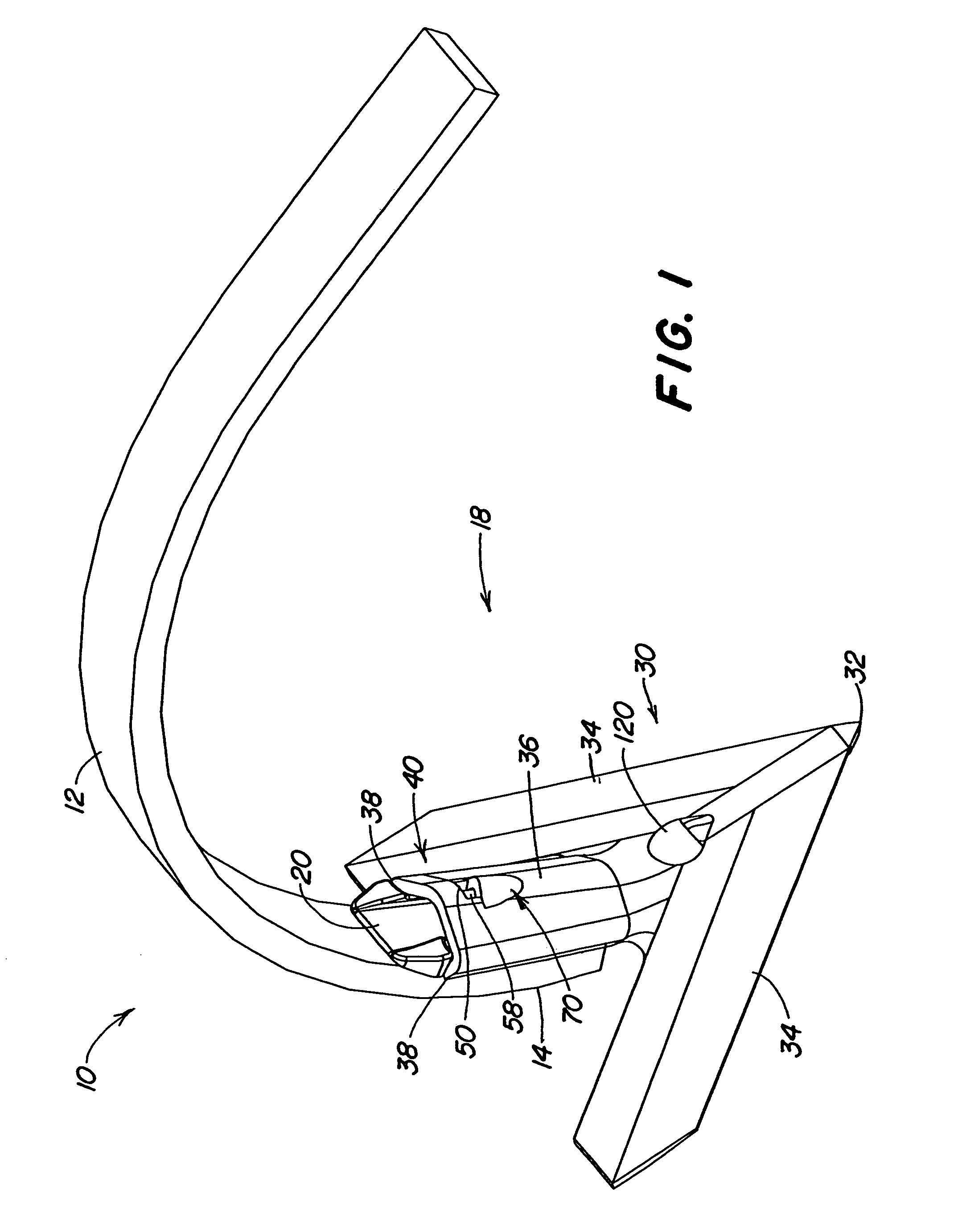
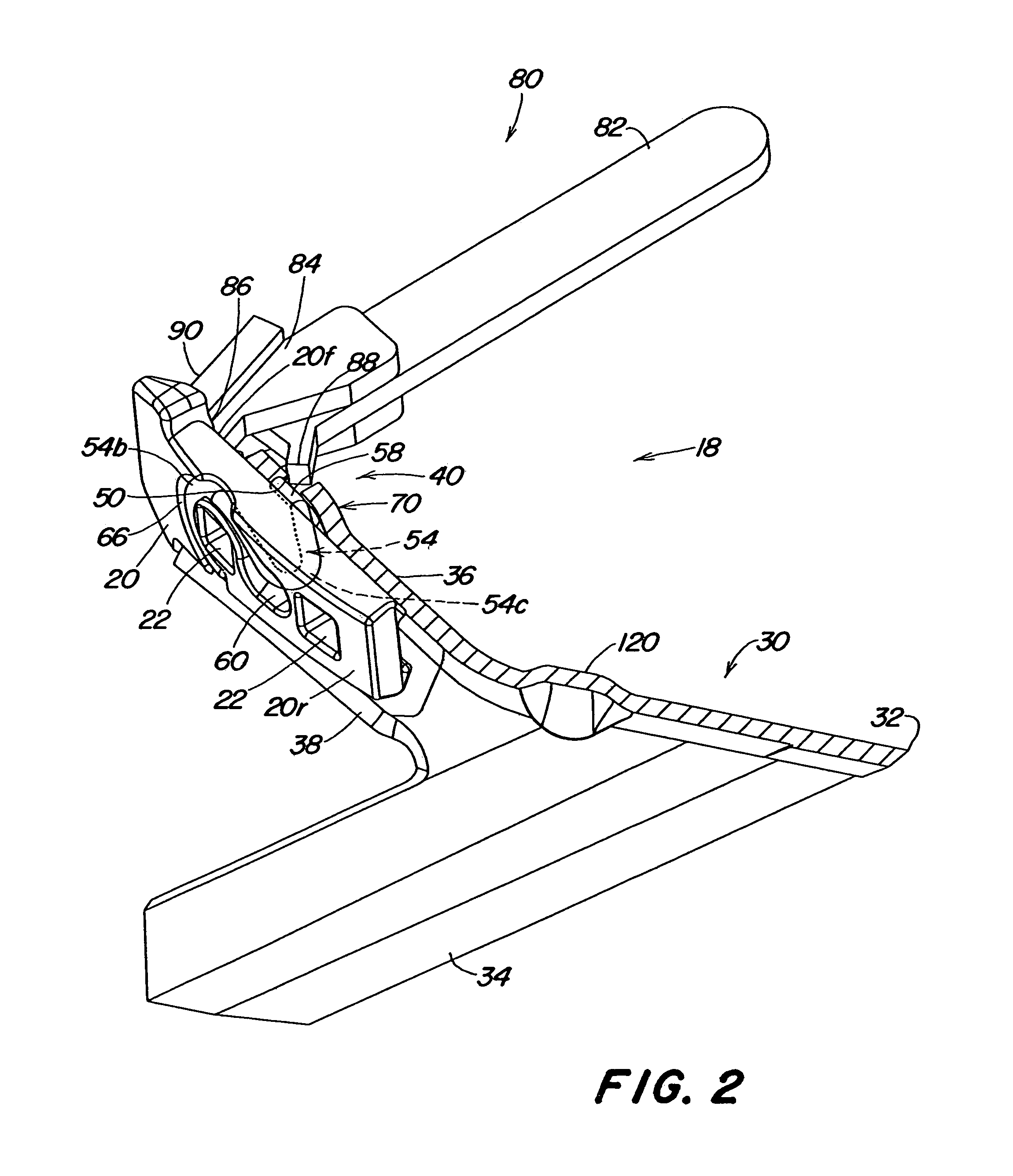
[0020]Referring now to FIG. 1, therein is shown the lower portion of a spring trip shank assembly 10 including a shank 12 having a lower tool-mounting end 14 supporting a knock-on sweep assembly 18. The assembly 18 includes a wedge-shaped adapter bracket or sweep support 20 having an aft face conforming to the forward face of the end 14. The support 20 is secured to the end by two plow bolts (not shown) extending through apertures 22 (FIG. 2) in the sweep support 20 and corresponding apertures in the end 14 of the shank 12. An earthworking tool 30, shown as a sweep in FIGS. 1 and 2, includes a forwardmost tip or point 32 and opposed wing portions 34 diverging outwardly in the rearward direction. An downwardly and rearwardly concave sweep mounting portion or stem 36 includes edges 38 which wrap partially around the bracket 20. The portion 36 provides a wedge fit between the tool 30 and the lower end 14 of the shank 12 when the tool 30 is knocked on the sweep support 20. The portion 3...


PUM

PropertyMeasurementUnit
areaaaaaaaaaaa
forcesaaaaaaaaaa
movementaaaaaaaaaa

Abstract

Sweep retaining structure includes a spring wire retainer with a base supported in a groove on the underside of the wedge support which mates with a stem portion of the sweep. The wedge support is apertured, and a central curved portion of the retainer passes through the aperture and supports a sweep-contacting end above the surface of the wedge support. The end is biased toward a contact area on the sweep to engage the area and eliminate sweep loss problems by preventing the sweep from slipping downwardly from the mounted position. To remove the sweep, a tool is inserted through the slot to depress the retainer end, and the sweep is forced off the wedge support. A raised area on the sweep directs soil away from the retainer and contact area to reduce wear and eliminate depression of the end during operation. The underside of the raised area positions the wire end and provides bend-resisting support for the wire.

Description

[0001]This is a continuation of application Ser. No. 10 / 376,162 filed 28 Feb. 2003, now U.S. Pat. No. 6,938,700 which is a continuation of application Ser. No. 09 / 982,901 filed 19 Oct. 2001, now U.S. Pat. No. 6,585,058, that application incorporated by reference in its entirety in this present application.FIELD OF THE INVENTION[0002]The present invention relates generally to tillage tools and, more specifically, to a knock-on sweep and structure for preventing the sweep from falling off the end of a shank.BACKGROUND OF THE INVENTION[0003]Standard assemblies for implements such as chisel plows and field cultivators typically include a spring trip shank assembly extending downwardly to a tool-receiving end which mounts a shovel, point or sweep. Previously available mounting structure included bolts extending through holes in the tool and the shank to secure the tool. When the tool in such an assembly has to be replaced because of wear or damage, the bolts must be removed. Wear and cor...

Claims


Application Information

Patent Timeline
Patent Type & Authority Patents(United States)
IPC IPC(8): A01B35/20
CPCA01B35/225Y10T29/53896
Inventor ZAUN, RICHARD DAVIDPOUTRE, BENOITPECK, DONALD RAYBEECK, MARKHOOK, RICHARD WAYNEVANAUWELAER, JAMES MICHAELRUCKLE, JARROD RAY
Owner DEERE & CO
Why Eureka
Try Eureka