
Anti-scattering X-ray shielding for CT scanners

a technology of ct scanners and shielding x-rays, which is applied in the direction of instruments, diaphragms/collimeters, and radiation diagnostic diaphragms, etc., can solve the problem of reducing the height to which as foils can be manufactured, generating measurement errors provided by other detectors, and reducing the quality of an image provided by ct scanners

Inactive Publication Date: 2007-06-26
KONINKLIJKE PHILIPS ELECTRONICS NV
View PDF12 Cites 24 Cited by
  • Summary
  • Abstract
  • Description
  • Claims
  • Application Information

AI Technical Summary

Benefits of technology

The present invention relates to an improved system for shielding X-ray detectors in a detector array of a multislice CT scanner from scattered X-rays. The invention provides AS shielding using foils along at least two different directions, including both z-axis and s-axis foils. The added s-axis foils provide efficient added shielding against scattered X-rays resulting from the relatively large dimension, thickness, of the fan-beam of the multislice scanner along the z-axis. The AS shielding configuration is similar for each X-ray detector, reducing possible artifacts in the image caused by differences in the energy spectrum of X-rays reaching different detectors. The invention also includes optional positioning of the AS material between the rows or columns of detectors, and the use of thin foils shaped to follow the shape of the detectors.

Problems solved by technology

If these scattered X-rays are incident on the other X-ray detectors, they can generate error in measurements provided by the other detectors and degrade quality of an image provided by the CT scanner.
However, a height to which AS foils can be fabricated is limited by production tolerances.
Shadowing alters the detection efficiency of a shadowed X-ray detector and may generate artifacts in images generated by the multislice CT scanner.
In addition, shadowing, when it exists, is often unstable and may change from time to time.
As a result, it can be difficult to compensate images provided by the CT scanner for artifacts introduced by shadowing.
It is noted that because of the geometry of fourth generation CT scanners, it is generally not possible to provide anti-scattering shielding for detectors comprised in a fourth generation CT scanner that does not result in undesirable shadowing of the detectors.
As a result anti-scattering shielding is usually not provided for fourth generation scanners.
For multislice scanners, as the number of slices simultaneously imaged increases, the problem of scattering error is exacerbated As it does not seem possible to deal with the problem simply by increasing the height of AS foils used to shield the detectors, new solutions to scattering error are required.

Method used


Image

  • Anti-scattering X-ray shielding for CT scanners
  • Anti-scattering X-ray shielding for CT scanners
  • Anti-scattering X-ray shielding for CT scanners

Examples


Embodiment Construction

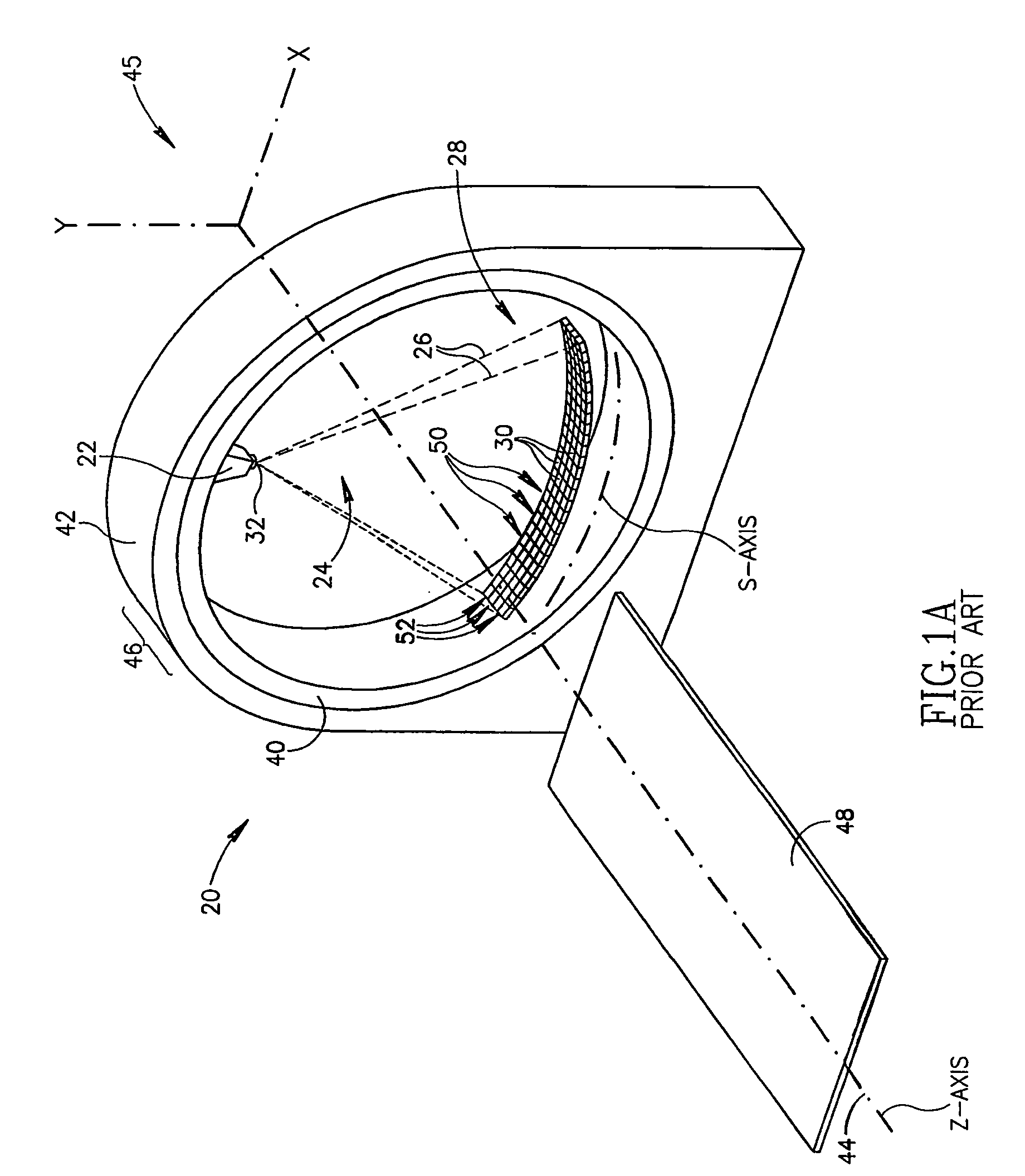
[0036]FIG. 1A schematically shows a third generation multislice CT scanner 20, in accordance with prior art. Only those features and components of CT scanner 20 germane to the present discussion are shown in FIG. 1A.

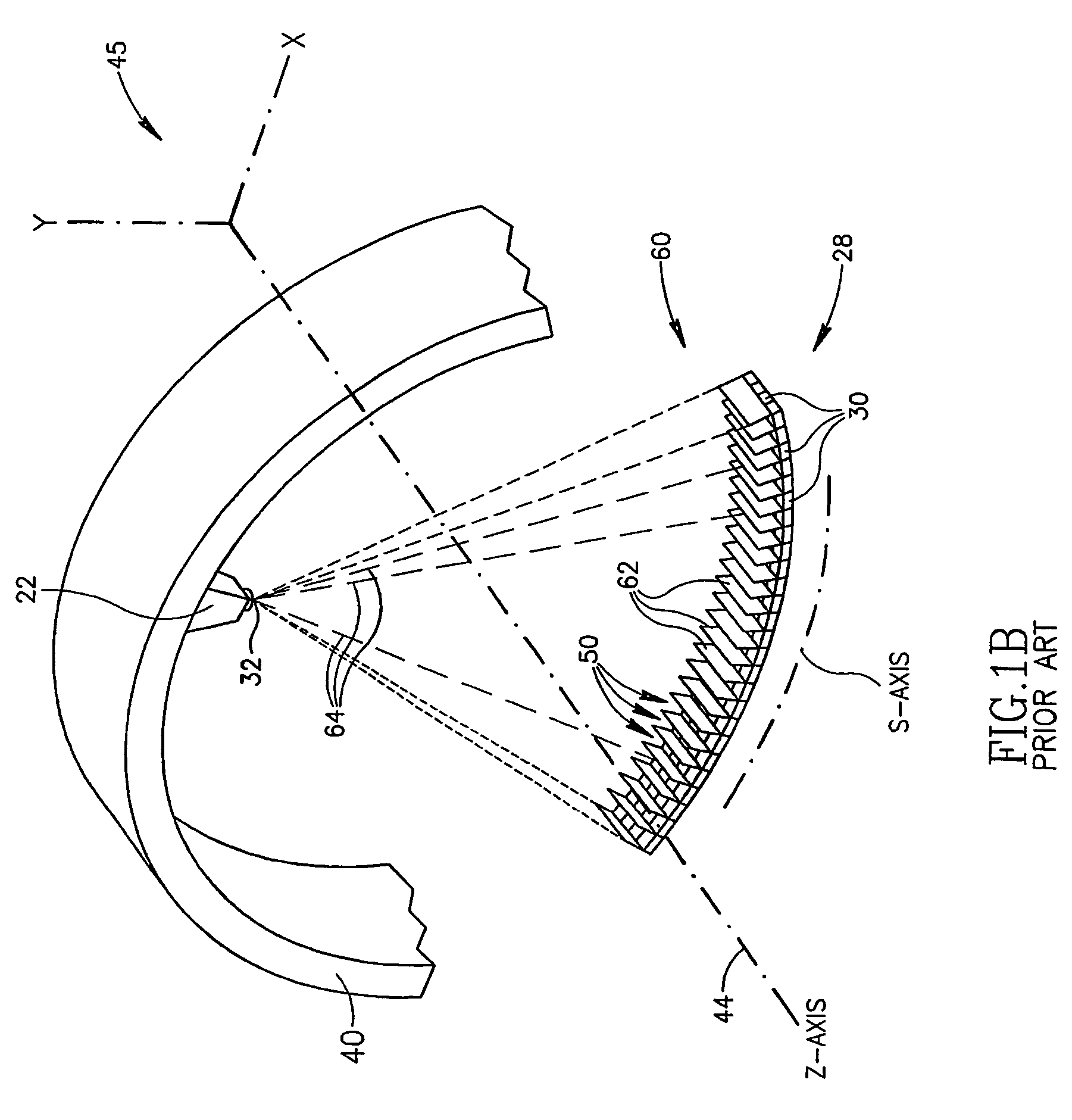
[0037]CT scanner 20 comprises an X-ray source 22 controllable to provide an X-ray fan-beam 24, schematically indicated by dashed lines 26, and an array 28 of X-ray detectors 30. Fan-beam 24 emanates from a focal region 32, hereinafter referred to as “focal spot 32”, of X-ray source 22. X-ray source 22 and detector array 28 are mounted to a rotor 40, which in turn is rotatably mounted to a stator 42 so that the rotor can be rotated about an axis 44 conveniently labeled as the z-axis of a coordinate system 45. Stator 42 and rotor 40 are components of a gantry 46 of CT scanner 20.

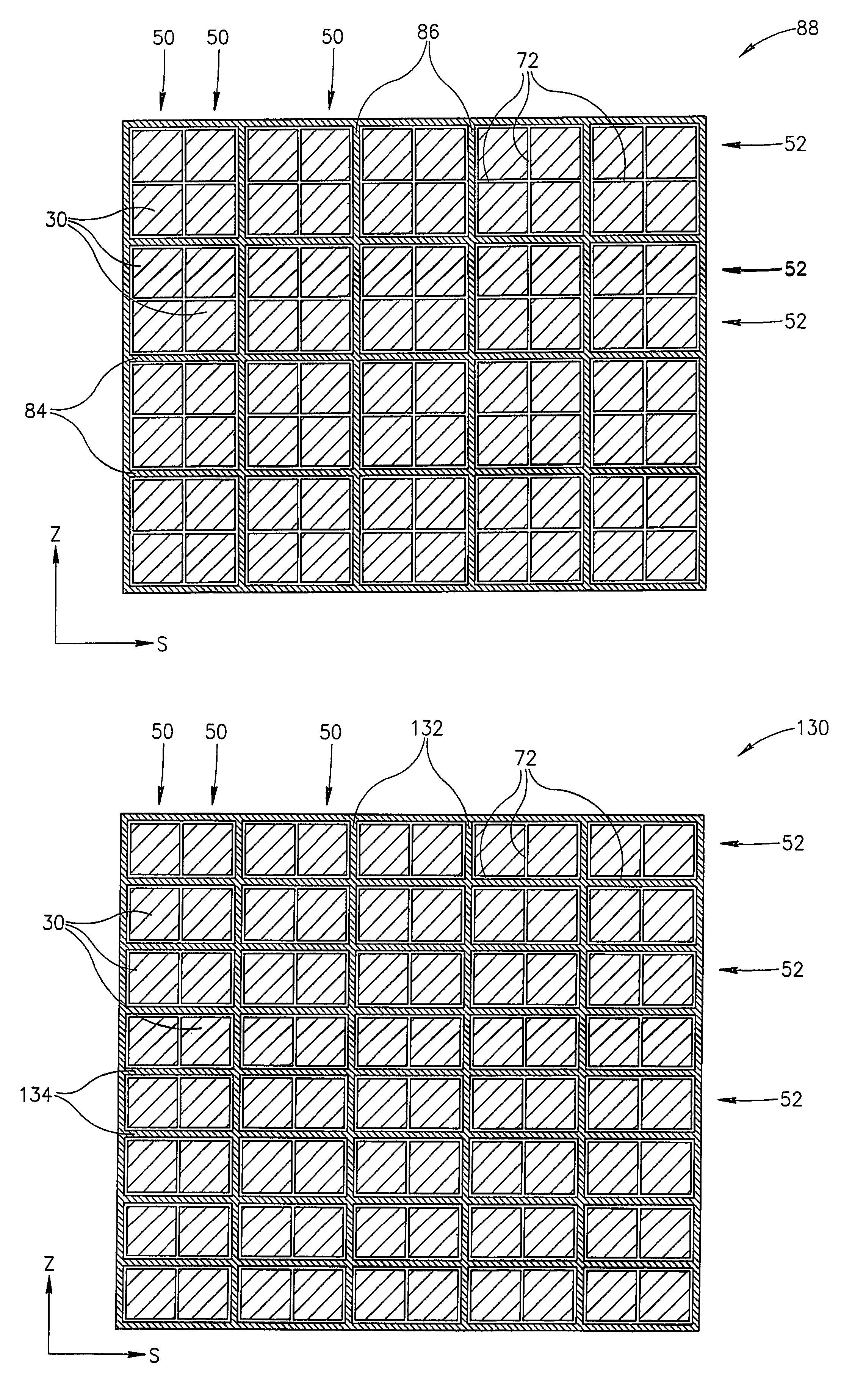
[0038]Array 28 has columns 50 and rows 52 of X-ray detectors 30. Array 28 is shown having four rows 52 of detectors to indicate, by way of example, that CT scanner 20 is a multislice scanner capabl...


PUM

PropertyMeasurementUnit
angleaaaaaaaaaa
heightaaaaaaaaaa
thicknessaaaaaaaaaa

Abstract

A CT scanner comprising a stator and a rotor having an axis of rotation mounted to the stator so that the rotor is rotatable about the axis of rotation comprising: an X-ray source mounted to the rotor, said X-ray source having a focal spot from which X-rays emanate; an X-ray detector array comprising a matrix of rows and columns of X-ray detectors; anti-scattering (AS) material for absorbing X-rays positioned between columns of the X-ray detectors; and anti-scattering (AS) material for absorbing X-rays positioned between rows of the X-ray detectors, whereby the AS material is located between every other row and / or column of detectors, respectively. Furthermore, the thickness and / or height of the foils between rows may be different from the thickness and / or height of the foils between columns.

Description

FIELD OF THE INVENTION[0001]The present invention relates to computerized tomography (CT) X-ray imaging and in particular to methods for shielding X-ray detectors in a CT imaging system from scattered X-rays.BACKGROUND OF THE INVENTION[0002]In CT X-ray imaging of a patient, X-rays are used to image internal structure and features of a region of the person's body. The imaging is performed by a CT-imaging system, hereinafter referred to as a “CT scanner” that images internal structure and features of a plurality of contiguous, relatively thin planar slices of the body region using X-rays.[0003]The CT scanner generally comprises an X-ray source that provides a planar, fan-shaped X-ray beam emanating from a focal spot of the X-ray source and an array of closely spaced X-ray detectors that are substantially coplanar with the fan-beam and face the X-ray source. The X-ray source and array of detectors are mounted in a gantry so that a person being imaged with the CT scanner, generally lyin...

Claims


Application Information

Patent Timeline
Patent Type & Authority Patents(United States)
IPC IPC(8): G01N23/00A61B6/03A61B6/06G01N23/04G21K1/02G21K1/10
CPCA61B6/032A61B6/4085A61B6/5282G21K1/025G21K1/10G01N23/046G01N2223/419
Inventor MALAMUD, GABRIEL
Owner KONINKLIJKE PHILIPS ELECTRONICS NV
Learn More