Ribbon spool lock assembly

a technology of spool lock and spool, which is applied in the direction of typewriters, printing, inking apparatus, etc., can solve the problems that existing approaches fail to address all of these problems

Inactive Publication Date: 2007-06-26
BURROUGHS CORP
View PDF14 Cites 9 Cited by
  • Summary
  • Abstract
  • Description
  • Claims
  • Application Information

AI Technical Summary

Benefits of technology

[0007]It is an object of the invention to provide an improved ribbon spool lock assembly in which the operator can only replace the ribbon by a series of steps which are designed-into the mechanism and which cannot be deviated from.

Problems solved by technology

Offset-type printing mechanisms typically require that depleted spools of ribbon media be replaced at regular integrals by less-skilled personnel.
Existing approaches fail to address all of these concerns.
Existing approaches typically require operators to learn and remember a specific routine of steps for ribbon replacement, deviation from which will lead to problems.

Method used


Image

  • Ribbon spool lock assembly
  • Ribbon spool lock assembly
  • Ribbon spool lock assembly

Examples


Embodiment Construction

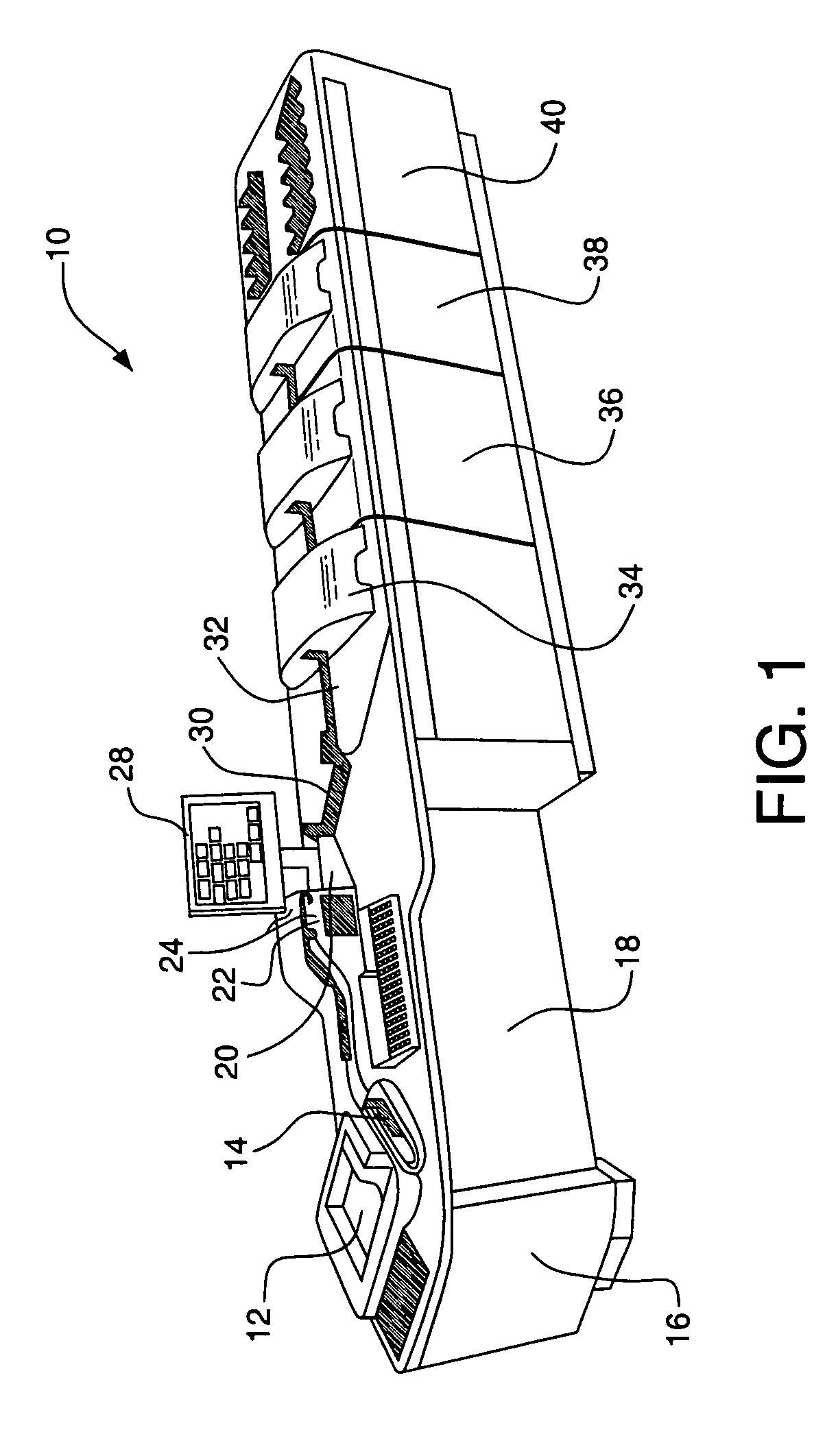
[0025]FIG. 1 illustrates a document processing system for feeding and transporting documents at 10. System 10 includes a primary feeder 12 and a secondary feeder 14. Cabinet 16 houses a computer running software for system 10. System 10 further includes removable kneewell panel 18. The feeders act to separate and feed documents singly, in order, from a stack. The remainder of the system is the transporting portion of the system, which includes a number of roller pairs and / or belts to convey the documents, one at a time, through a track past other processing devices that perform operations on the documents.

[0026]As shown in FIG. 1, a number of processing devices are located in the transporting portion of the system 10. Magnetic ink character recognition (MICR) reader 20 and optical character recognition (OCR) reader 22 are located in the document track following secondary feeder 14. As well, upstream imaging devices 24 image each passing document. The operator display is indicated at...


PUM


Abstract

A printing mechanism requires ribbon spools to be locked in place radially, and includes a pivoting ribbon tension arm that must be pivoted out of its normal operating position when ribbon is to be replaced. A ribbon spool lock assembly includes a rotating locking hub on the side of the printing mechanism. The rotating locking hub includes a locking feature that protrudes into the printing mechanism to radially lock the ribbon spool when the locking hub is in a locked position. A pivoting lock arm is provided for pivoting the locking hub into an unlocked position in which the locking feature is disengaged from the ribbon spool.

Description

BACKGROUND OF THE INVENTION[0001]1. Field of the Invention[0002]The invention relates to offset-type printing mechanisms for high-speed printing of magnetic ink character recognition (MICR) symbols which use a conventional spool of print ribbon.[0003]2. Background Art[0004]Offset-type printing mechanisms typically require that depleted spools of ribbon media be replaced at regular integrals by less-skilled personnel. Because such printing mechanisms typically include spring tensioner, guide and locking elements to ensure correct installation, location and control of the ribbon and ribbon replacement mechanisms must be designed with an eye to swift, self-evident and foolproof ways of replacing ribbon for minimum downtime.[0005]Existing approaches fail to address all of these concerns. Existing approaches typically require operators to learn and remember a specific routine of steps for ribbon replacement, deviation from which will lead to problems.[0006]For the foregoing reasons, ther...

Claims


Application Information

Patent Timeline
Patent Type & Authority Patents(United States)
IPC IPC(8): B41J35/08
CPCB41J17/32B41J33/003B41J35/28
Inventor TRATAR, DAVID B.
Owner BURROUGHS CORP
Why Eureka
Try Eureka