
Preheating cold blast air of a blast furnace for tempering the hot blast temperature

Inactive Publication Date: 2007-06-19
AKER KVAERNER METALS
View PDF11 Cites 7 Cited by
  • Summary
  • Abstract
  • Description
  • Claims
  • Application Information

AI Technical Summary

Benefits of technology

[0009]The present invention is of most interest to those sites where excess blast furnace gas is being flared and the stove performance is deteriorating. The invention is a viable option for raising hot blast temperature and extending stove life when there is not sufficient economic incentive to repair the stoves. The preheater may be built while the blast furnace continues to operate and the capital cost may be less than the cost of a new stove. The present invention may also reduce the cost of producing molten metal at the blast furnace by recycling the lost energy of flared blast furnace gas or other wasted fuels back into iron production.

Problems solved by technology

But in many blast furnace systems the blast furnace stoves begin to deteriorate long before the end of the blast furnace campaign itself.
Deteriorating blast furnace stoves' heating capacity will diminish and as a result the hot blast air supplied to the blast furnace will not be sufficiently hot for optimal operation of the blast furnace.
The refractory work in the stove becomes plugged either from dirt in the blast furnace gas combustion products or falling and crumbling brickwork.
But, repairs to a stove generally can be carried out only after the stove is cooled to near ambient temperature, which means that the stove can not be operating.
This long interruption to the operation of the stove substantially affects the blast furnace's economical operation.

Method used


Image

  • Preheating cold blast air of a blast furnace for tempering the hot blast temperature
  • Preheating cold blast air of a blast furnace for tempering the hot blast temperature
  • Preheating cold blast air of a blast furnace for tempering the hot blast temperature

Examples


Embodiment Construction

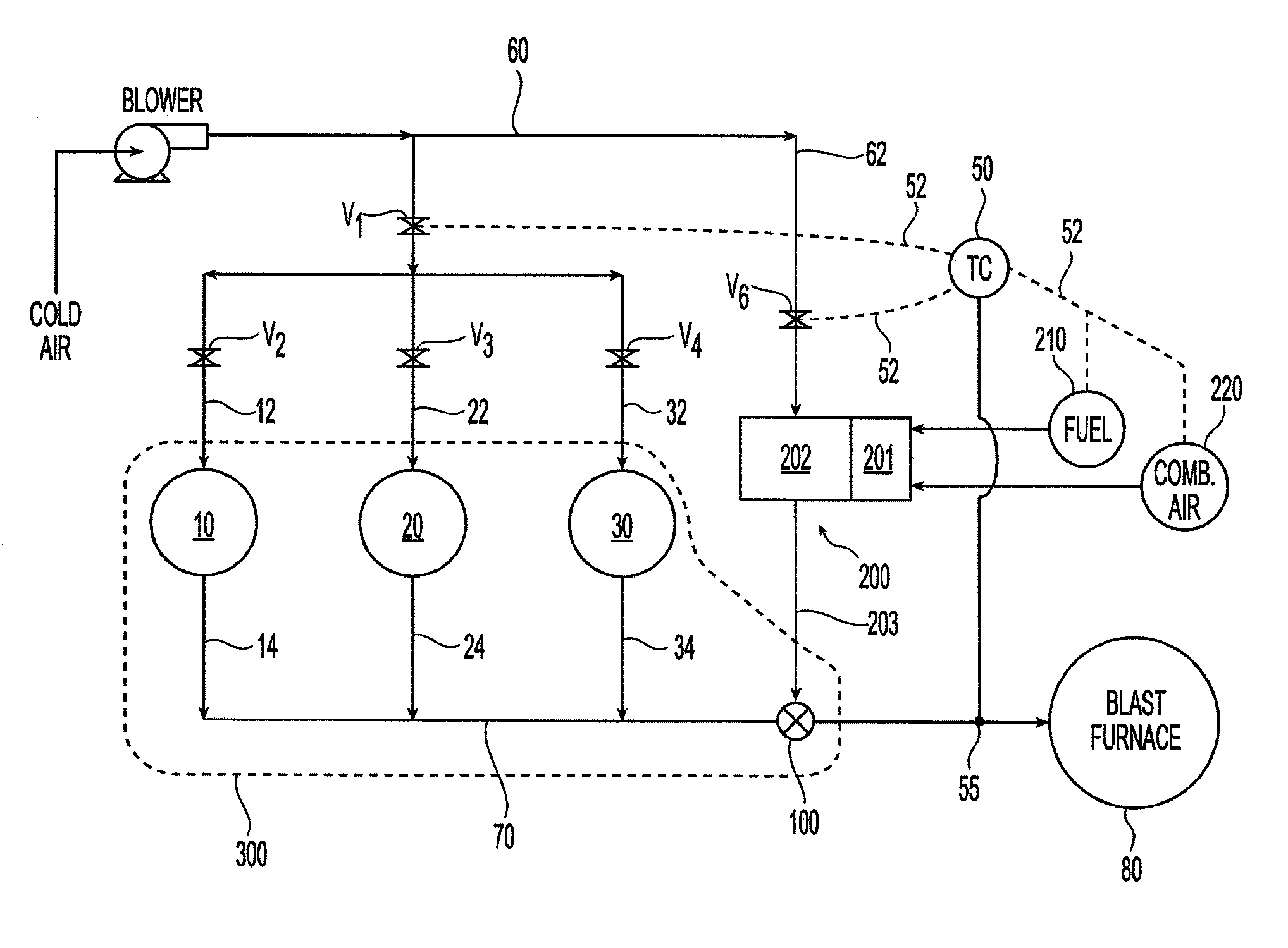
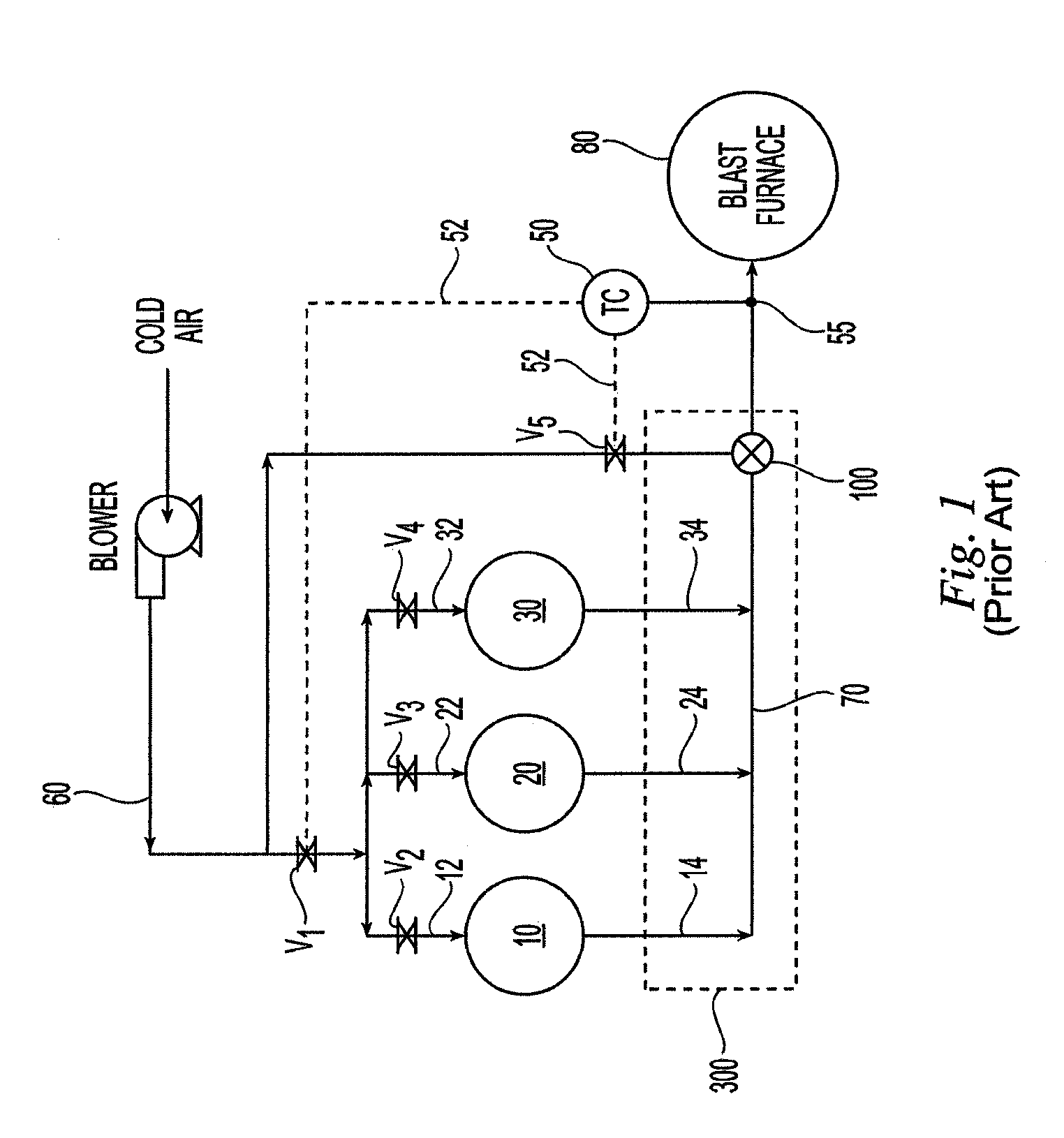
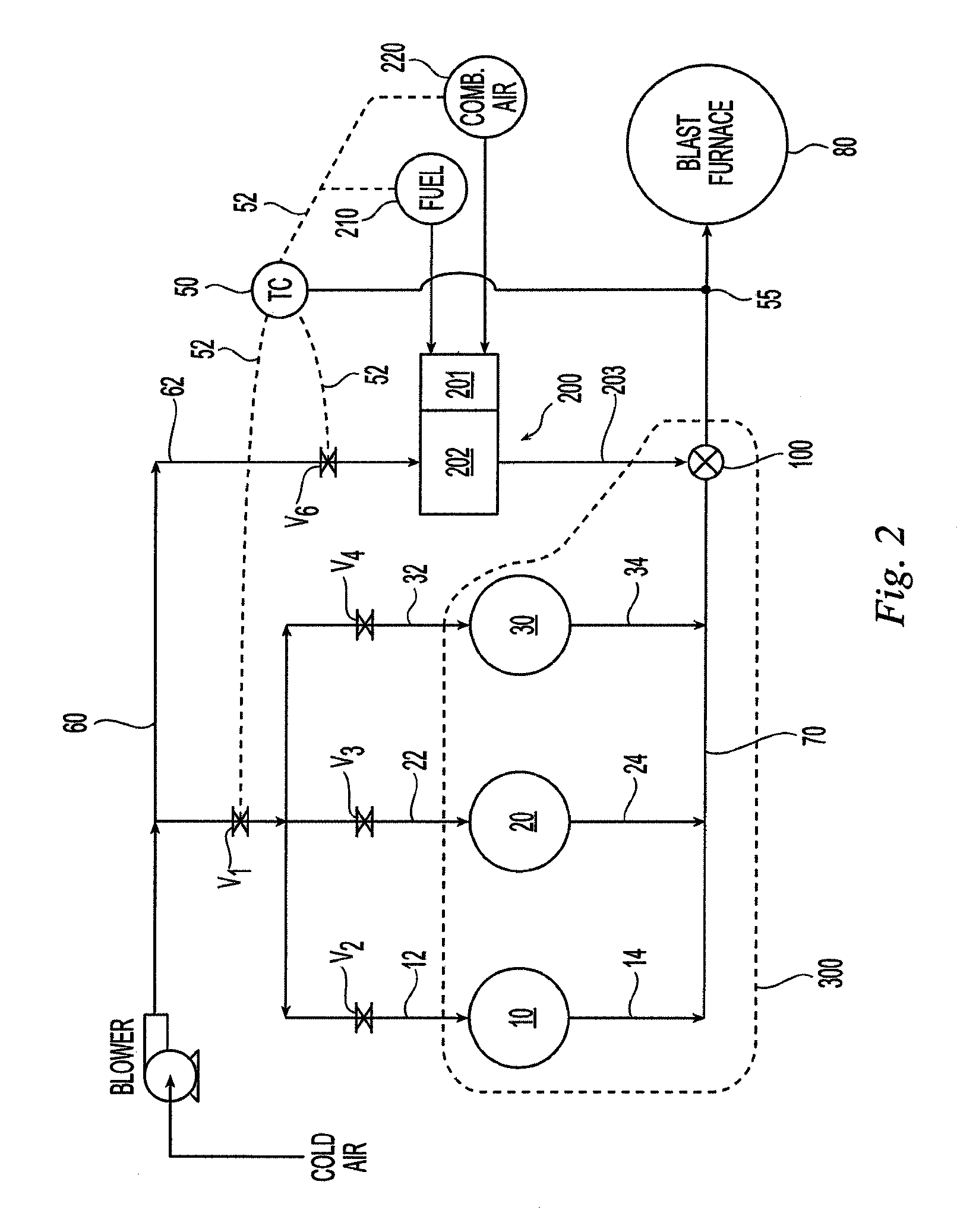
[0020]To help describe the various embodiments of the present invention, a conventional blast furnace system will be first described. FIG. 1 is a schematic illustration of a conventional blast furnace system having stoves 10, 20, 30. Blast furnace systems generally have a plurality of stoves and usually three or more The stoves heat the cold air (cold blast) that supplies the oxygen to convert the carbon in the coke to carbon monoxide and heat required for the transformation of iron ore to molten iron. The heated air supplied to the blast furnace is known as hot blast. The cycles of the stove heating process are: 1) heating the refractory brickwork (checkers) known as “on heat”, and 2) heating the cold blast known as “on blast”. During the on heat cycle, the stoves burn combustion fuel, generally excess blast furnace gas, in their combustion chambers to heat the stoves' checkers. The cold blast from the cold blast main 60 enters the stoves 10, 20, 30 via supply lines 12, 22, 32 and ...


PUM

PropertyMeasurementUnit
Temperatureaaaaaaaaaa
Flow rateaaaaaaaaaa

Abstract

An improved blast furnace system for producing molten iron incorporating a preheater to heat the cold blast air used to temper the hot blast temperature is disclosed. The improved blast furnace system comprises a blast furnace, a hot blast main for conveying a supply of hot blast to the blast furnace, a plurality of stoves for heating a supply of cold blast and generating the hot blast, a cold blast main for conveying a supply of cold blast to the plurality of stoves, and at least one cold blast preheater for heating a portion of the cold blast, that has been diverted to the preheater, into heated air and the heated air is mixed with the hot blast to temper the hot blast temperature.

Description

FIELD OF THE INVENTION[0001]The present invention relates to a blast furnace system for producing molten iron. More particularly, the present invention relates to an improved blast furnace system incorporating a preheater to heat the cold blast air used to temper the hot blast temperature and to methods of tempering the hot blast temperature using preheated cold blast air.BACKGROUND OF THE INVENTION[0002]In a blast furnace system, a plurality of blast furnace stoves is operated at time-displaced cycles to heat a blast of air used to provide heat for a blast furnace. In each stove, there is a vertical combustion chamber coupled to a burner to inject gas, usually excess blast furnace gas, and air into the bottom portion of the chamber for combustion. Each stove is alternately on gas (being heated by combustion of the blast furnace gas) or on blast (heating the cold blast air). The combustion products are directed by a dome from the top of the combustion chamber into a regenerator thro...

Claims


Application Information

Patent Timeline
IPC IPC(8): C21B13/00C21B11/02C21B5/00C21B5/06C21B9/14
CPCC21B5/006C21B5/06C21B9/14C21B2100/64Y02P10/25
Inventor FRIEDRICH, MICHAELD'ARRIGO, ROBERT
Owner AKER KVAERNER METALS
Learn More