
Multiple view angles camera, automatic photographing apparatus, and iris recognition method

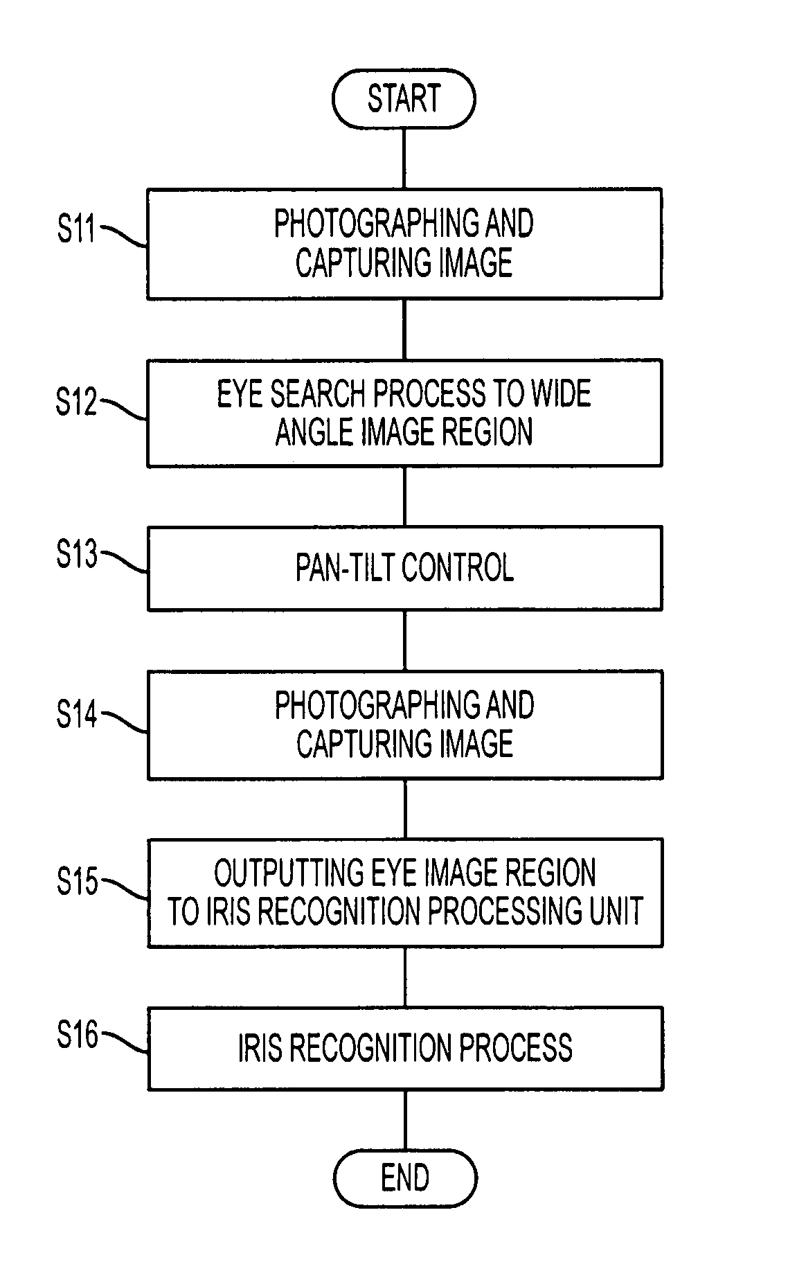
a technology of automatic photographing and iris recognition, which is applied in the field of multi-view angle cameras, automatic photographing apparatus, and iris recognition methods, can solve the problems of large size of the camera unit which includes two cameras, heavy weight of the camera, and complex circuit for processing image signals therefor, so as to reduce size and cost

Inactive Publication Date: 2007-06-12
OKI ELECTRIC IND CO LTD
View PDF6 Cites 37 Cited by
  • Summary
  • Abstract
  • Description
  • Claims
  • Application Information

AI Technical Summary

Benefits of technology

[0008]Therefore, it is the object of the present invention to provide a multiple view angles camera, an automatic photographing apparatus, and an iris recognition method which overcome the above issues in the related art in order to reduce the size and weight of the camera unit, and the cost of the automatic photographing apparatus, in particular the iris recognition apparatus. This object is achieved by combinations described in the independent claims. The dependent claims define further advantageous and exemplary combinations of the present invention.
[0012]In accordance with the present invention structured in the foregoing, since the multiple view angles camera which projects the wide view angle image and the narrow view angle images on one image sensor, is included, only one camera is required for its operation although two cameras have been required conventionally, and further it is made possible to reduce the size and cost.

Problems solved by technology

Therefore, there has been a problem in which the size of the camera unit which include two cameras has been large and the weight thereof has been heavy.
Further, since the image signals have been output from each camera, a circuit for processing the image signals therefor has come to be complex.
As a result, there has been a problem in which the cost of the automatic photographing apparatus, in particular the iris recognition apparatus, has come to increase.

Method used


Image

  • Multiple view angles camera, automatic photographing apparatus, and iris recognition method
  • Multiple view angles camera, automatic photographing apparatus, and iris recognition method
  • Multiple view angles camera, automatic photographing apparatus, and iris recognition method

Examples


first embodiment

[0038]The first embodiment is explained.

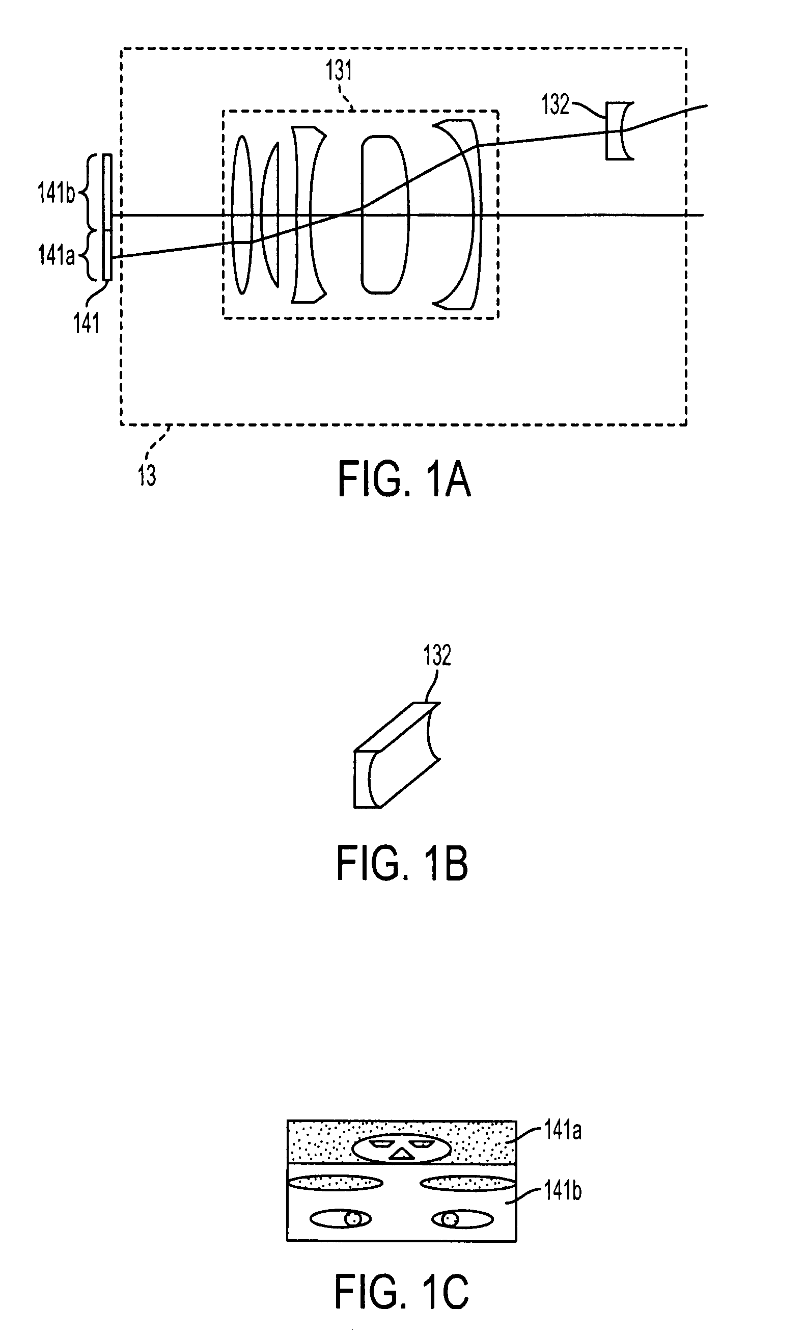
[0039]FIGS. 1A to 1C illustrate a multiple view angles camera. Prior to the explanation thereto, an automatic camera system using the multiple view angles camera is explained.

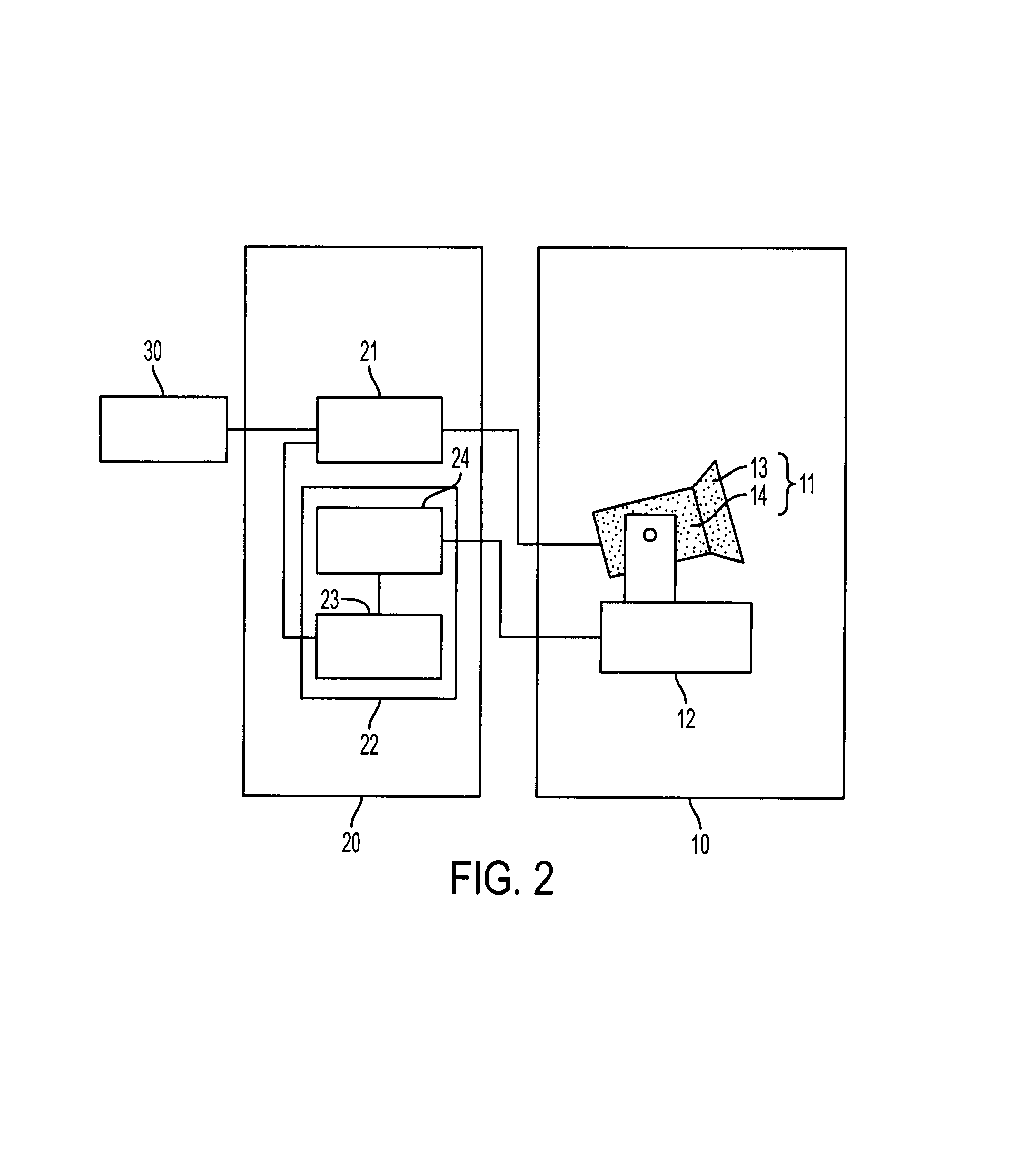
[0040]FIG. 2 is a block diagram of the first embodiment of the automatic camera system of the present invention.

[0041]The system of FIG. 2 shows the structure which is applied to an iris recognition system which performs iris recognition using the automatic camera system.

[0042]The system of FIG. 2 includes a camera 10, a control unit 20, and an iris recognition processing unit 30.

[0043]The camera 10 includes a multiple view angles camera 11 and a pan-tilt mechanism 12. The multiple view angles camera 11 is a high definition camera and includes a multiple view angles lens 13 and a camera body 14. The multiple view angles lens 13 is a lens having a function for projecting a wide view angle photograph region and a narrow view angle photograph region as a wide view angle imag...

second embodiment

[0071]Next, the second embodiment is explained.

[0072]The second embodiment is a multiple view angles camera, which photographs an image of a wide view angle photograph range and an image of such a narrow view angle photograph range.

[0073]FIG. 6 is a block diagram of the second embodiment.

[0074]The system of FIG. 6 includes a camera unit 10a, the control unit 20, and the iris recognition processing unit 30. Here, since the structure of the control unit 20 and the iris recognition processing unit 30 is the same as the first embodiment, the same reference number is used to the corresponding part and thus the explanation therefor is omitted.

[0075]The camera unit 10a includes a multiple view angles camera (a face and eye image camera) 11a and the pan-tilt mechanism 12, and the pan-tilt mechanism 12 is the same as the first embodiment. For the multiple view angles camera 11a, the different point from the multiple view angles camera 11 of the first preferred embodiment is the structure of ...

third embodiment

[0092]Next, the third embodiment is explained herein.

[0093]In the third embodiment, the embodiment is structured in such a way that two narrow view angle photograph ranges are photographed by the multiple view angles camera and the two regions thereof are changeable.

[0094]FIG. 10 is a block diagram of the third embodiment.

[0095]The system of FIG. 10 includes a camera unit 10b, a control unit 20a, and the iris recognition processing unit 30. Here, since the structure of the iris recognition processing unit 30 is the same as the first and second embodiments, the explanation therefor is omitted.

[0096]The camera unit 10b includes a multiple view angles camera (a face and eye image camera) 11b and a pan-tilt mechanism 12, and the pan-tilt mechanism 12 is the same as the first and second embodiments. On the other hand, the point in which the multiple view angles camera 11b differs from the multiple view angles camera 11a of the second embodiment is in that the reflecting angle of the pris...


PUM


Abstract

A multiple view angles camera used for an automatic photographing apparatus includes a narrow view angle lens, a cylinder lens, and an image sensor. One image sensor is used, and a wide view angle image and a narrow view angle image are projected on the image sensor at the same time. The narrow view angle lens projects the image of the eye photograph range on an eye image region on the image sensor. The cylinder lens is a wide view angle lens and projects the image of a wide view angle photograph range on a wide view angle image region on the image sensor by way of this cylinder lens and the narrow view angle lens.

Description

BACKGROUND OF THE INVENTION[0001]1. Field of the Invention[0002]The present invention relates to a multiple view angles camera for taking wide view angle photographs and a narrow view angle photographs of a specific subject, an automatic photographing apparatus for photographing using this multiple view angles camera, and an iris recognition method for performing iris recognition using this automatic photographing apparatus.[0003]2. Description of the Related Art[0004]As an iris recognition apparatus, an iris recognition apparatus using the automatic photographing apparatus has been known. The automatic photographing apparatus used for the iris recognition apparatus photographs, first of all, the facial image of a subject standing in front of the apparatus by way of a wide view angle camera. Next, the subject's eye position is automatically detected from this facial image. Then, based on the eye position thus detected, a pan-tilt mechanism aim the narrow view angle camera which is m...

Claims


Application Information

Patent Timeline
Patent Type & Authority Patents(United States)
IPC IPC(8): G06K9/00G03B15/00H04N5/225H04N5/232H04N7/18
CPCG06K9/00597G06K9/00604G06V40/18G06V40/19
Inventor NAHATA, KENJI
Owner OKI ELECTRIC IND CO LTD
Learn More