Voltage equalization method and apparatus for low-voltage lighting systems

a technology of voltage equalization and low-voltage lighting, applied in lighting devices, light sources, climate sustainability, etc., can solve problems such as voltage drop along the bus lin

Inactive Publication Date: 2007-06-05
GAETA CELESTINO JOHN +2
View PDF13 Cites 7 Cited by
  • Summary
  • Abstract
  • Description
  • Claims
  • Application Information

AI Technical Summary

Problems solved by technology

However, in practice there is always a finite resistivity in the bus lines, which results in a voltage drop along the bus line when current is flowing.

Method used


Image

  • Voltage equalization method and apparatus for low-voltage lighting systems
  • Voltage equalization method and apparatus for low-voltage lighting systems
  • Voltage equalization method and apparatus for low-voltage lighting systems

Examples


Embodiment Construction

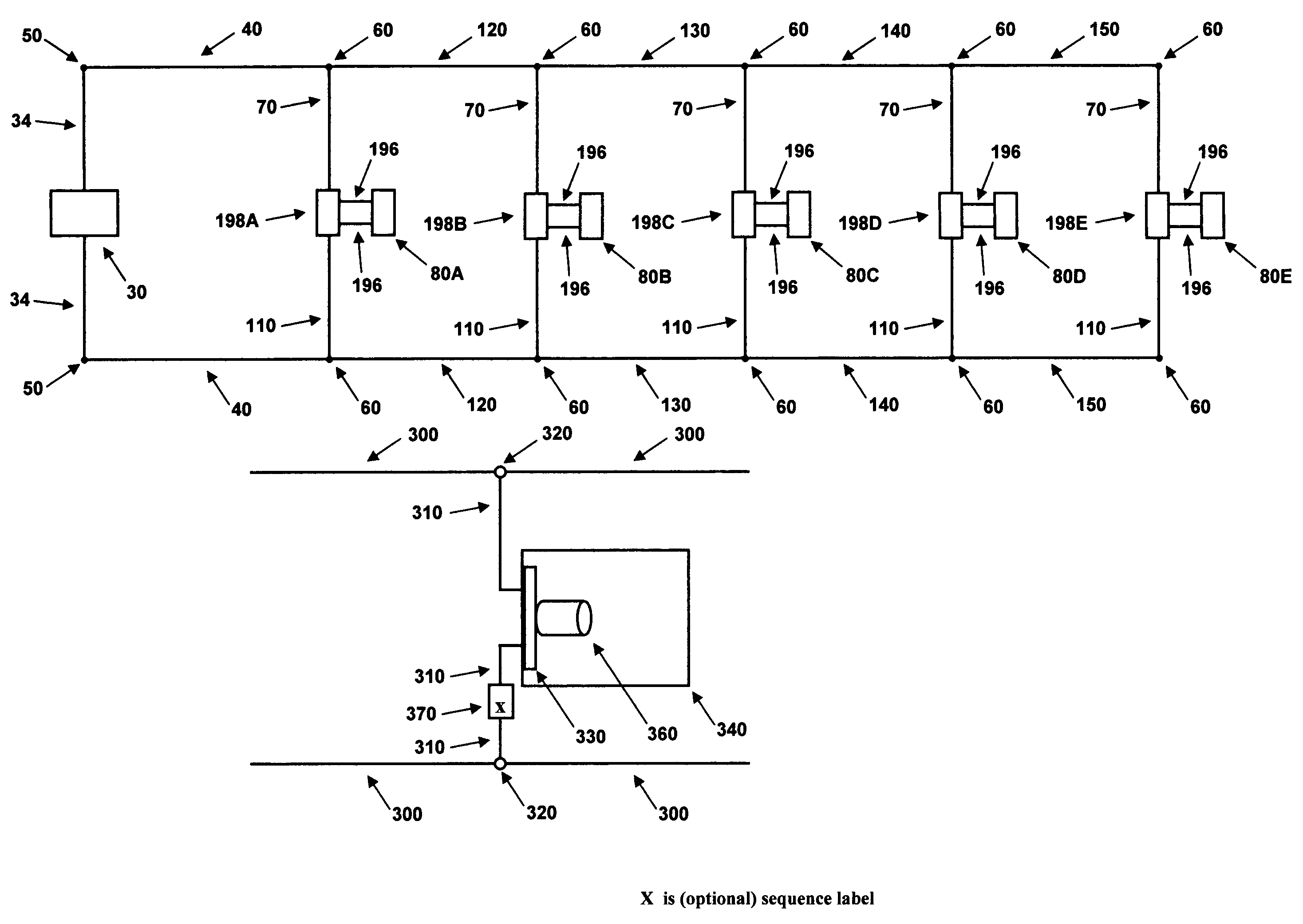
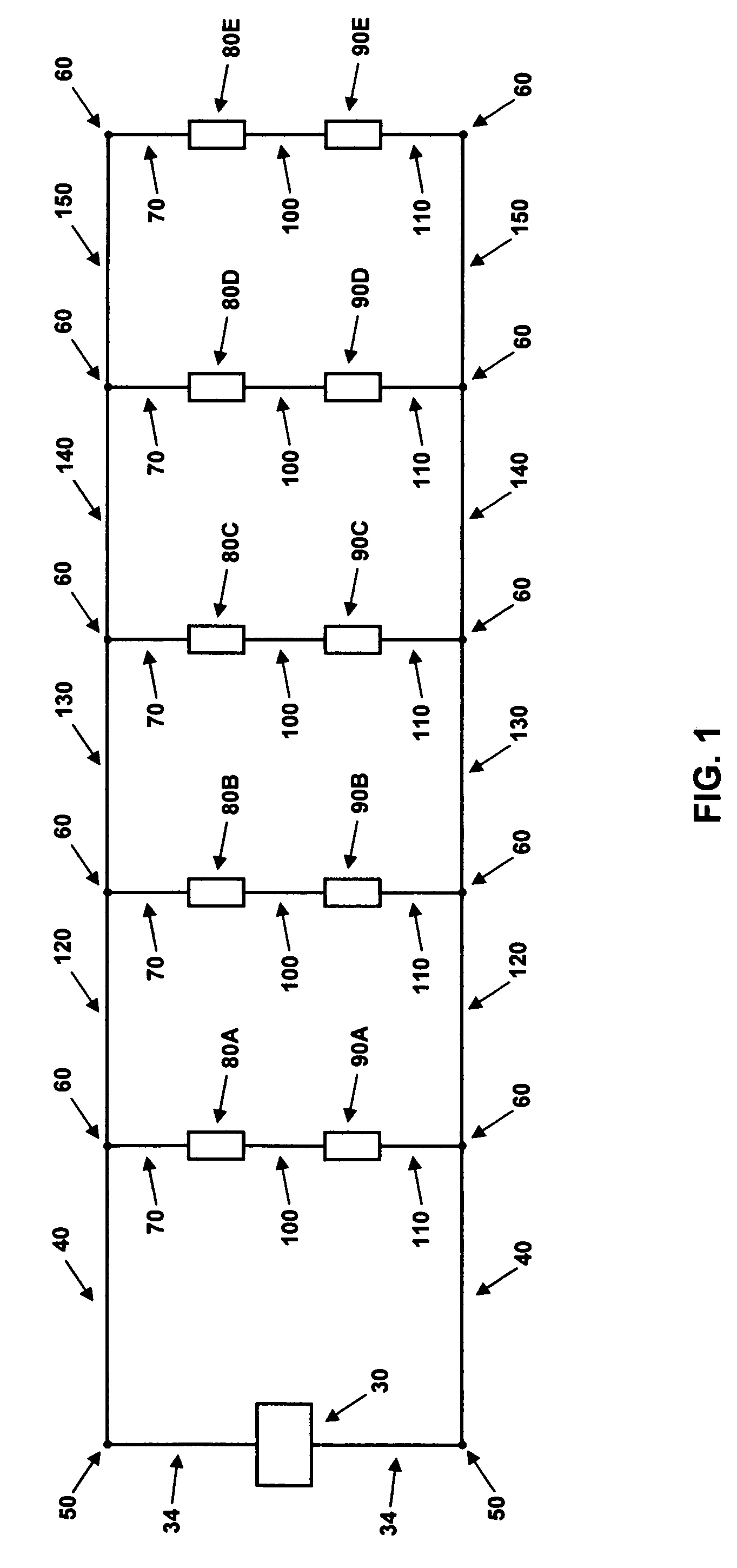
[0031]A low-voltage lighting system with five light bulbs of the same power and voltage ratings (internal resistance) will be used as a representative example in order to facilitate the explanation of the current invention without loss of generality. The results will then be generalized to an arbitrary number N of light bulbs, electrically connected in parallel with the power source. In the preferred embodiment, the current invention is comprised of an adjustable resistance placed electrically in series with each light bulb, as well as the method of determining the required value of the resistance for equalizing the power in each light bulb. FIG. 1 depicts a block diagram of the electrical description for the example low-voltage lighting system.

System Description

[0032]An electrical power source 30 with electrical connectors 34 is attached to electrical conductors 40 via connection nodes 50. One of the conductors 40 is connected, via a connection node 60, to an electrical connector 7...


PUM


Abstract

A method and apparatus to equalize the voltage across each light bulb in a low-voltage lighting system, commonly found in the yards of private homes and businesses. The present invention consists of a power compensation element that is inserted in-line with each light bulb connected to the bus lines that distribute current from a power source, such as an electrical transformer, to the light bulbs. The function of the power compensation element is to compensate for the voltage drop along the bus lines due primarily to the electrical resistance of the bus lines. Therefore, a compensation rating of the power compensation element may depend upon its location along the bus lines and the electrical resistivity of the bus lines, as well as the internal electrical resistance of the light bulbs. The preferred embodiment is an electrical resistive power compensation element where the rating of the element is its resistance value. One alternate embodiment is an electrical transformer power compensation element where the rating is the transformer ratio of output-to-input voltage, while another alternate embodiment is a diode-based, voltage-limiting circuit power compensation element, typically with equal rating where the rating is the voltage-limiting reference level of the circuit.

Description

CROSS-REFERENCE TO RELATED APPLICATIONS[0001]NoneFEDERALLY SPONSORED RESEARCH[0002]Not ApplicableSEQUENCE LISTING OR PROGRAM[0003]Note ApplicableBACKGROUND OF THE INVENTION[0004]1. Field of the Invention[0005]The present invention relates generally to low voltage lighting systems, and more specifically to systems which have long bus lines to deliver current to low voltage light bulbs located along the length of the bus lines.[0006]2. Prior Art[0007]At present, low-voltage lighting systems distribute current from a common power source to each light bulb in a parallel configuration. In other words, a wire (bus line) from the power source is connected to one end of several light bulbs along its length to distribute current in parallel to each light bulb. The product of the current and internal resistance of each light bulb is equal to the voltage drop across the light bulb; according to Ohm's law. Note that devices, concepts, and physical laws, such as Ohm's law, used in the theory of ...

Claims


Application Information

Patent Timeline
Patent Type & Authority Patents(United States)
IPC IPC(8): H05B37/00
CPCH05B39/044Y02B20/146Y02B20/00
Inventor GAETA, CELESTINO JOHNMIXON, CURTISS LYNNSHINTAKU, LARRY
Owner GAETA CELESTINO JOHN
Why Eureka
Try Eureka