
System and method for optical detection of petroleum and other products in an environment

a technology of optical detection and petroleum, applied in the field of system and method for optical detection of petroleum and other products in an environment, can solve the problems of increasing the optical detection system cannot distinguish the difference between aqueous and non-aqueous media through the use of conductivity sensors, and the dynamic expansion or contraction of the stored product, so as to reduce the cost and complexity of the sensor, and reduce the effect of false alarms

Inactive Publication Date: 2007-06-05
RGT UNIV OF CALIFORNIA
View PDF26 Cites 13 Cited by
  • Summary
  • Abstract
  • Description
  • Claims
  • Application Information

AI Technical Summary

Benefits of technology

The present invention is a system and method for detecting petroleum-based fluids, such as oil and lubricants, in a variety of environments using an optical detection system. The system is designed to use the unique fluorescence properties of petroleum-based compounds to detect the presence of these fluids. The system includes an excitation source, a detector, and an alarm system. The detector is tuned to the emission wavelengths of petroleum-based fluids, making it possible to distinguish them from other fluids. The system can be used in various optical applications, such as detecting cooling water leaks, monitoring medical applications, and assessing water and air quality. The invention provides a reliable and cost-effective solution for detecting petroleum-based fluids and preventing environmental hazards.

Problems solved by technology

Furthermore, temperature variation, which is a substantial factor, causes dynamic expansion or contraction of the stored product on both a short-term and long-term basis.
Currently available optical detection systems can only distinguish the difference between aqueous and non-aqueous media through the use of conductivity sensors.
Furthermore, these detection schemes are subject to environmental deterioration, thereby increasing the cost and complexity of the sensor.
Furthermore, conductivity sensors for leak detection lead to potential false positive alarms.

Method used


Image

  • System and method for optical detection of petroleum and other products in an environment
  • System and method for optical detection of petroleum and other products in an environment
  • System and method for optical detection of petroleum and other products in an environment

Examples


Embodiment Construction

[0027]Reference will now be made in detail to an exemplary embodiment of the present invention, an example which is illustrated in the accompanying drawing (FIGS. 1–12).

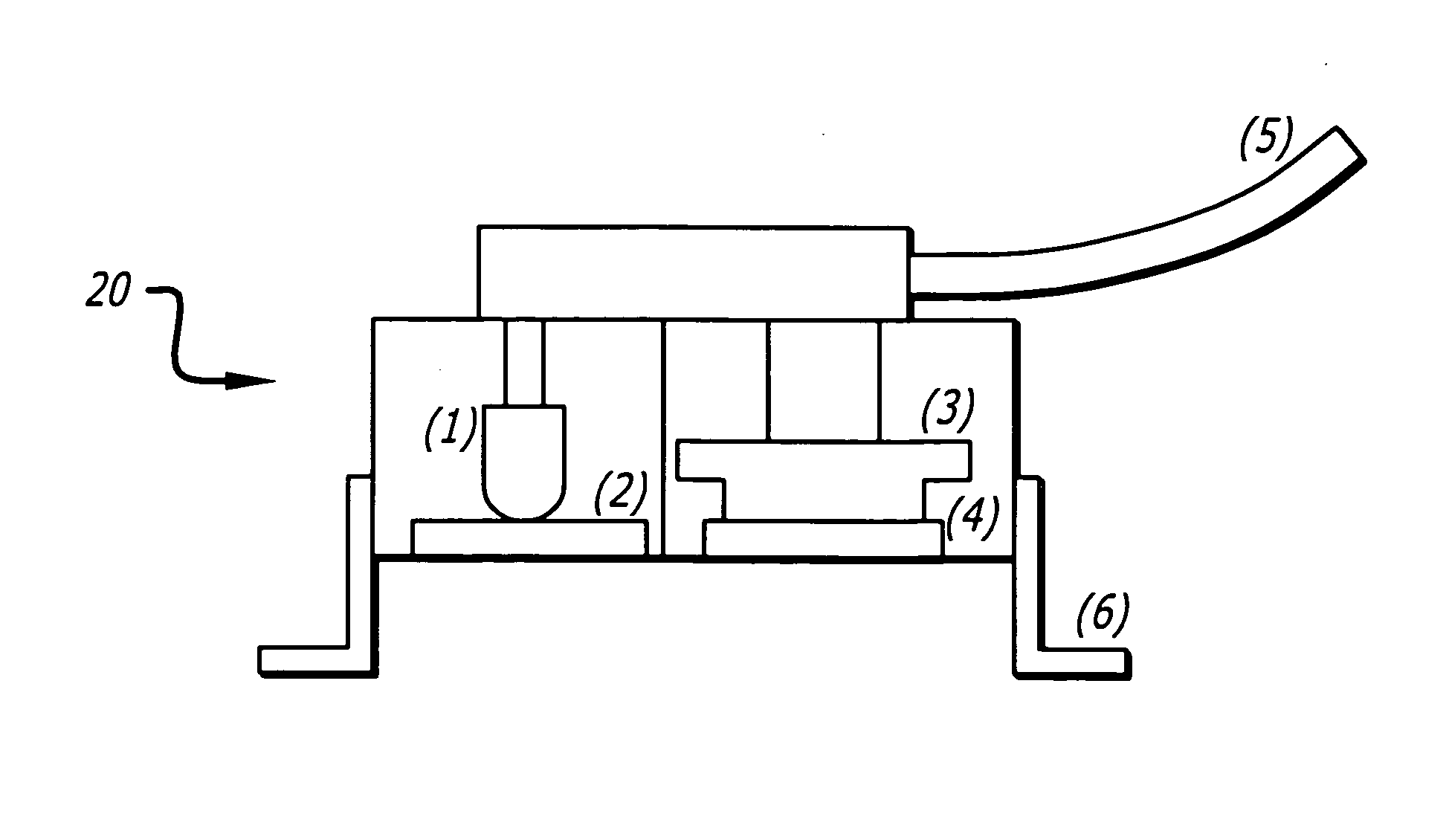
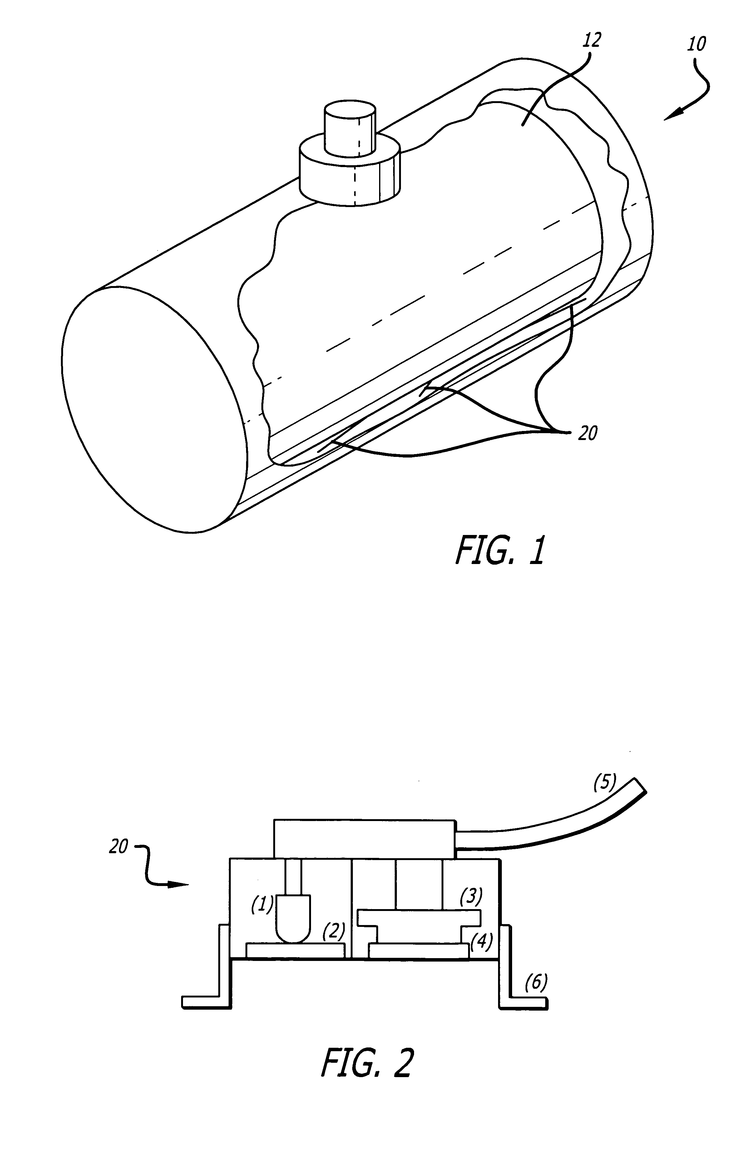
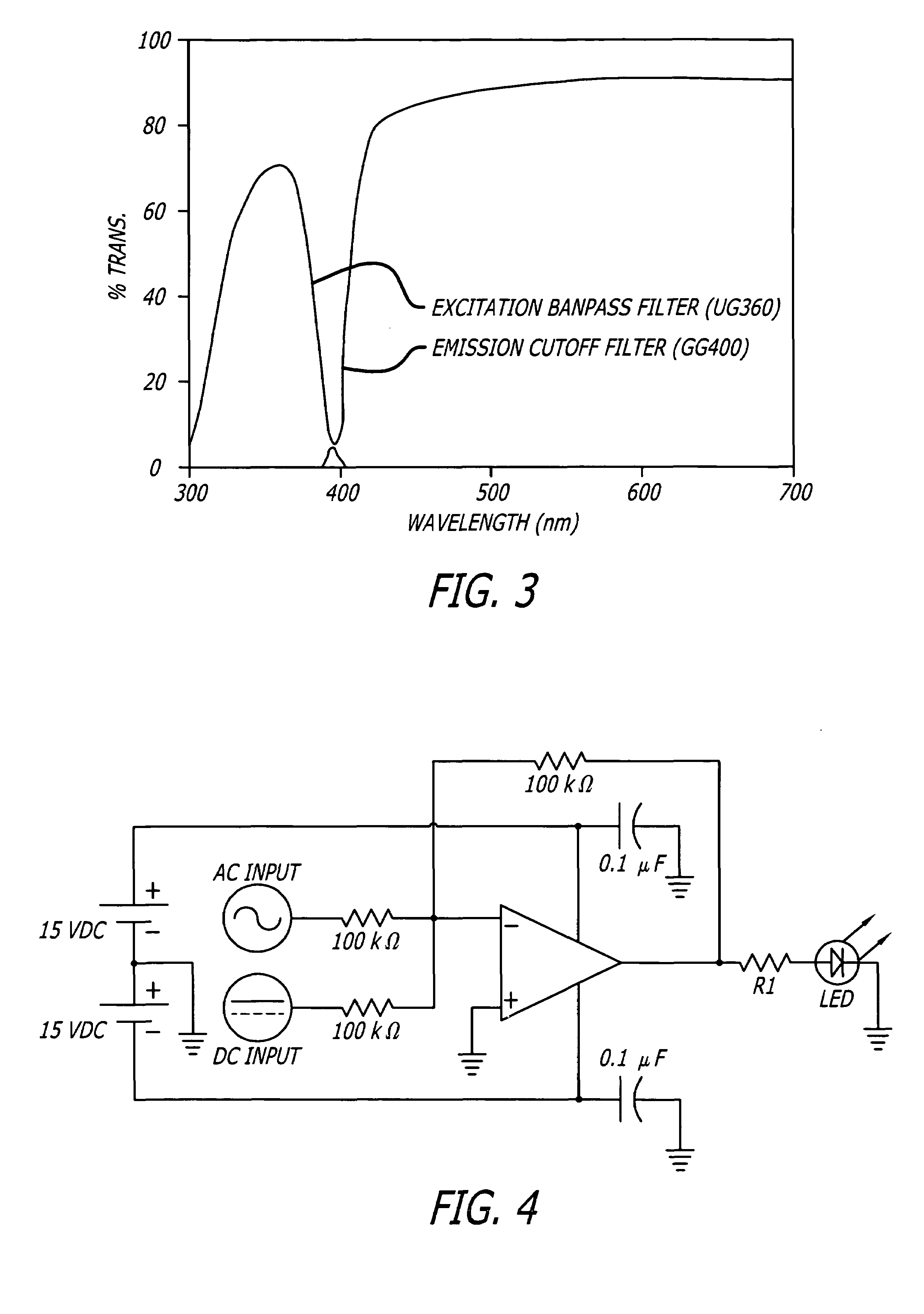
[0028]Optimal detection parameters are determined for several selected petroleum materials commonly found in underground and aboveground tanks (gasoline, fuel oils etc.) generally depicted as 12. Appropriate excitation and emission wavelengths are then selected for detecting specific petroleum based materials. The emission wavelengths generally vary depending on the petroleum product (in some cases these wavelengths are between 400 and 600 nm). In one aspect of the present invention, the excitation wavelengths may be in the ultra-violet region (e.g., 300–400 nm region) but may vary depending on the product to be detected. This information is used to determine off-the-shelf and customized devices for detecting petroleum liquid releases from the tank 12. The system of the present invention utilizes relatively inexpensi...


PUM

PropertyMeasurementUnit
frequencyaaaaaaaaaa
frequencyaaaaaaaaaa
volumeaaaaaaaaaa

Abstract

A system for detecting leaks of petroleum and other non-petroleum based products in an environment includes a sensor package comprising at least one LED and an optical photo-detector. The emitter transmits an excitation signal with an excitation wavelength, and the detector is tuned to the emission wavelengths of a fluorescing mixture, such as a petroleum based product, in a space where detection is sought. An alarm system coupled to the detector may be used for notifying users in case of a leak.

Description

CROSS-REFERENCE TO RELATED APPLICATIONS[0001]The contents of this application are a Continuation-In-Part of the U.S. application having Ser. No. 10 / 702,250 filed on Nov. 4, 2003 now abandoned and is incorporated by reference herein.BACKGROUND[0002]1. Field of the Invention[0003]The present invention relates generally to the use of optical sensors to detect the presence of petroleum and non-petroleum based liquids, fluids, or products in a sample, medium, or environment.[0004]2. General Background and State of the Art[0005]Systems and methods for detecting leaks of petroleum or other products, in an environment or medium, are well known in the prior art. Most of these techniques use a quantitative approach to identify a leak or to determine leak rate based on a measurement of volumetric changes of the product. The capability of prior art leak detection methods to accurately measure leakage is affected by certain variables such as temperature change, surrounding medium characteristics...

Claims


Application Information

Patent Timeline
Patent Type & Authority Patents(United States)
IPC IPC(8): G01N21/64G01M3/38
CPCG01M3/38
Inventor KRAM, MARKLAVERMAN, LEROY
Owner RGT UNIV OF CALIFORNIA
Learn More