
Socket with force applying member

Inactive Publication Date: 2007-06-05
TOPOWER COMP IND CO LTD
View PDF9 Cites 2 Cited by
  • Summary
  • Abstract
  • Description
  • Claims
  • Application Information

AI Technical Summary

Benefits of technology

[0005]In view of the drawbacks and limitations occurred to the conventional techniques, the present invention aims to provide a transmission line that can be easily plugged and unplugged to conform to the industrial specifications and to facilitate user operation.
[0006]The primary object of the invention is to provide a transmission line that is easily plugged and unplugged. It has a force applying member hinged on a socket. To remove the socket from an insertion slot, in can be easily accomplished by applying a force on the force applying member. The transmission line of the invention is adaptable to various types of connectors to improve operation convenience and enhance applicability in the industry.
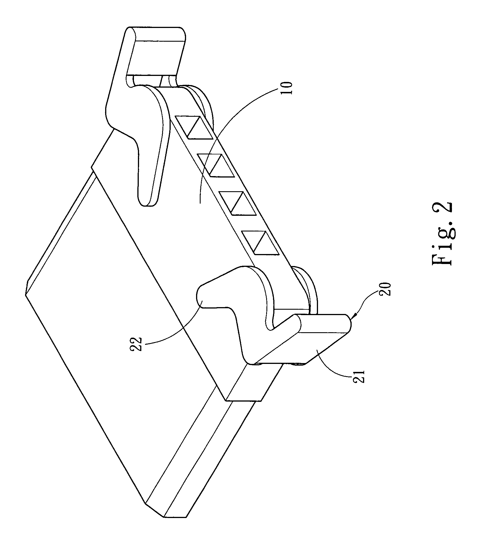
[0007]The transmission line of the invention includes a wire and at least one socket connecting to one end of the wire. The socket aims is connected to an electronic device and also is coupled with a force applying member. The force applying member rams the electronic device when subject to a force to make separation of the socket and the electronic device easier. The force applying member is hinged on the socket and divided by the hinged location to form a force applying portion and a pressing portion. When the force applying portion receives a force, the pressing portion generates a counter force about the hinged location to make separation of the socket and the electronic device easier. Hence by means of the construction set forth above, users can easily unplug the socket from the electronic device.

Problems solved by technology

Hence plugging and unplugging between the socket and the insertion slot generally are not easy and take a lot of efforts.
But even resorting to the protrusive members still is difficult to overcome the tight coupling between the socket and the insertion slot to remove the socket from the insertion slot.
This could cause damage of the connection terminal and dislocation.
As a result, plugging next time could be difficult and poor contact could occur.
This is troublesome to users.
This results in not equal potential of the disconnected electronic device and the power supply, and the floating voltage rises.
In addition to the disadvantages mentioned above, a slight arc occurs due to the male and female fire terminals do not share the common ground.
This phenomenon increases the impedance of the fire terminals and affects electric characteristics.
If the connector previously discussed is adopted on the SATA socket, the pressing plate will hinder the vertically inserting wires and coupling becomes not possible.
In other words, the connector mentioned in the previous patent cannot be adopted on the SATA socket.
Thus its applicability is limited.

Method used


Image

  • Socket with force applying member
  • Socket with force applying member
  • Socket with force applying member

Examples


Embodiment Construction

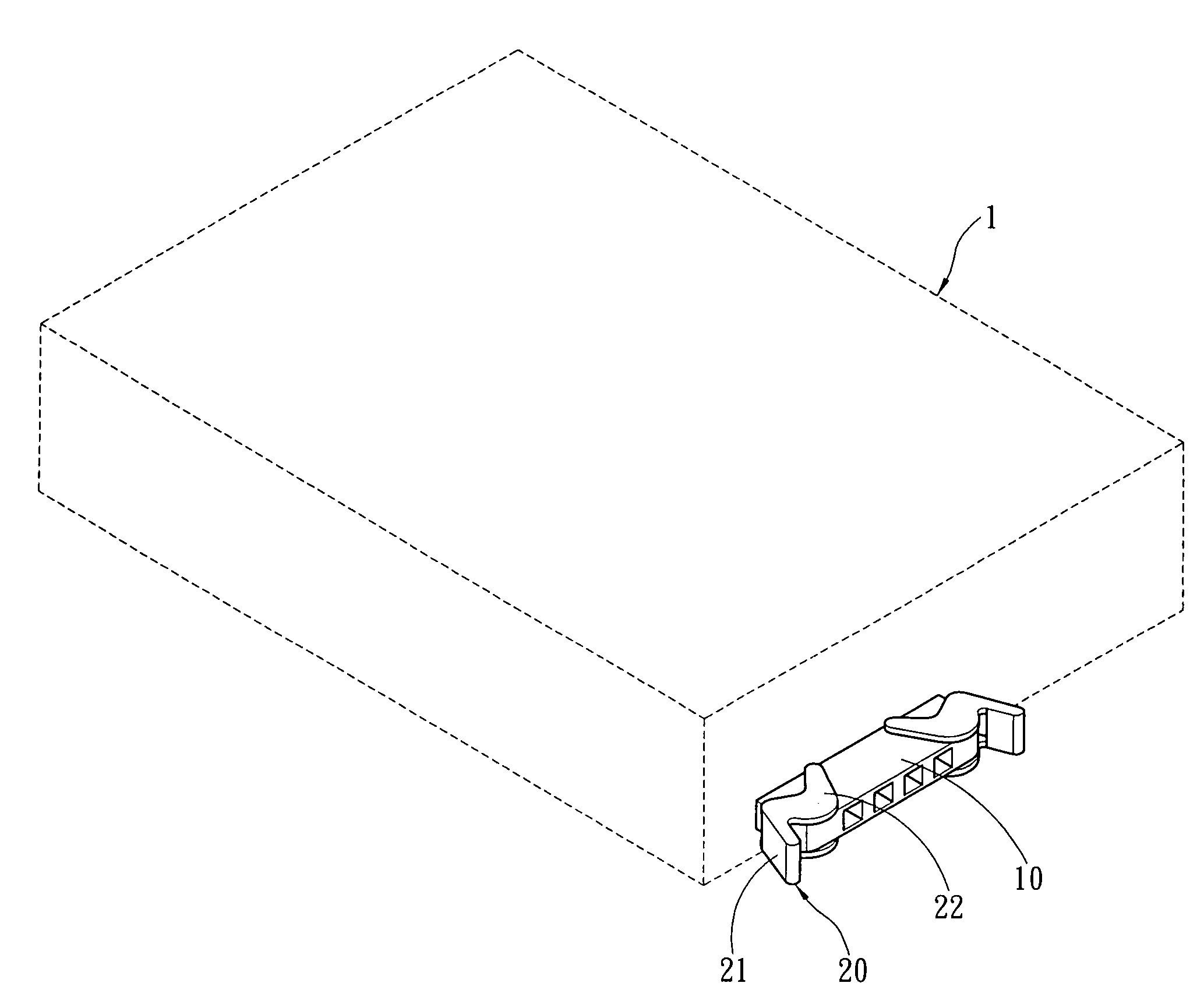
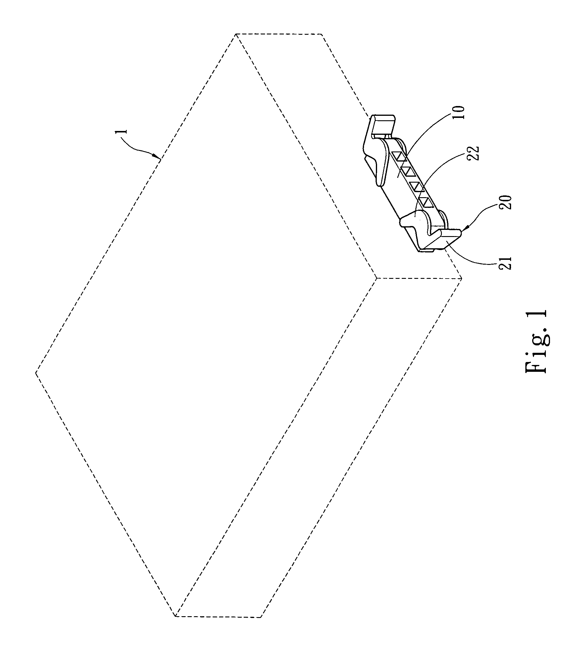
[0016]Please refer to FIGS. 1, 2 and 3 for the invention in a use condition and the perspective and exploded views. The transmission line according to the invention includes a wire and at least a socket 10 connecting to one end of the wire. The wire may be a conventional one, and forms no part of the invention, thus is not shown in the drawings. The socket 10 is coupled with an electronic device 1 which may be a computer peripheral device (such as hard disk drive or the like) or other electronic devices. The socket 10 is coupled with a force applying member 20 which presses the electronic device 1 when subject to a force to make the socket 10 to be separated easily from the electronic device 1. The force applying member 20 is hinged on the socket 10. The force applying member 20 has an anchor boss 23. The socket 10 has a retaining hole 11 corresponding to the anchor boss 23 to be hinged by the force applying member 20 (or an axle may be provided to form the hinge effect). The force ...


PUM


Abstract

A transmission line that is plugged and unplugged includes a wire and at least one socket connecting to one end of the wire. The socket is connected to an electronic device and coupled with a force applying member. The force applying member rams the electronic device when subject to a force to facilitate separation of the socket and the electronic device. The force applying member is hinged on the socket and is divided by the hinged location to form a force applying portion and a pressing portion. When the force applying portion receives the force, the pressing portion generates a counter force about the hinged location against the electronic device to make the socket to be removed from the electronic device.

Description

FIELD OF THE INVENTION[0001]The present invention relates to a transmission line that is easily plugged and unplugged and particularly to a transmission line that has a force applying member hinged on a socket to facilitate plugging and unplugging.BACKGROUND OF THE INVENTION[0002]Nowadays computers are widely used in various industries or locations. The rapid advance of computer technology also constantly spawns new functions. For instance, multimedia applications need new peripheral devices such as CD-ROM optical drivers. The operation speed of the computers also is faster and produces higher temperature during operation. This requires a cooling fan to generate cooling airflow to dispel heat energy generated by the CPU chipset in the computer. These additional computer peripheral devices or cooling fan have to be coupled with a power supply socket on the computer to obtain power supply for operation.[0003]The socket and insertion slot of the computer peripheral devices have to be t...

Claims


Application Information

Patent Timeline
IPC IPC(8): H01R13/627
CPCH01R13/6335
Inventor CHEN, MICHAELLIN, TAI-WEI
Owner TOPOWER COMP IND CO LTD
Learn More