Pipe assembly unit with built-in flow sensors

a technology of flow sensor and assembly unit, which is applied in the direction of lighting and heating apparatus, heating types, instruments, etc., can solve the problems of difficulty in positioning with respect to the assembly direction in the connection, the length of the whole pipe is difficult to adjust, and the work is forced to be troublesome, so as to achieve excellent convenience, improve versatility, and raise the degree of freedom in the arrangement of the pipe arrangement

Active Publication Date: 2007-06-05
TOFLO CORP
View PDF15 Cites 10 Cited by
  • Summary
  • Abstract
  • Description
  • Claims
  • Application Information

AI Technical Summary

Benefits of technology

[0016]According to a pipe assembly unit with built-in flow sensors of the present invention, there is adopted a construction in which a pipe assembly which is integrally formed with a main pipe and multiple branch pipes is used and a flow sensor which detects the flow rate of a fluid flowing through each of the branch pipes is built in each of the multiple branch pipes. Therefore, in the connections of the main pipe and the branch pipes, it becomes unnecessary to use a conventional seal construction in which nipples, seal tape or seal parts such as liquid gaskets are used, and perfect sealing properties which prevent troubles of liquid leakage from occurring can be ensured. At the same time, the positioning accuracy of pipes during assembling and the dimensional accuracy of the length of pipes are remarkably raised. Also, by abolishing the use of sealing parts such as nipples, which have hitherto been necessary in the connection of pipes, it is possible to realize pipe savings and a reduction of the number of parts, and as a result of this, the burden on workers who perform piping work is reduced and equipment expenses can be reduced.
[0017]Because of the adoption of the essential feature that the flow sensor is a vane wheel sensor, in which a magnet is buried in an arbitrary fin of a vane wheel which rotates by the passage of a fluid and conversion to a flow rate value is performed on the basis of a frequency obtained by detecting the magnetism of the magnet by use of a magnetic sensor, the construction of the flow sensor is simplified, the work of attaching and detaching the flow sensor to and from the inside of the branch pipe becomes easy, and maintenance can be easily performed.
[0019]A substantial improvement in versatility is achieved, because an arbitrary number of pipe assembly units with built-in flow sensors in each of which two or three branch pipes are used are combined and the main pipes of the combined arbitrary number of units are connected so as to be able to serve piping lines of two or all numbers of systems.
[0020]The degree of freedom in the arrangement of piping is raised and excellent convenience is achieved, because by detachably attaching a pipe adapter having legs to the opening ends of the main pipe and fixing the legs to an installation surface by changing the direction of the adapter, whereby the mounting posture of the pipe assembly unit with built-in flow sensors is made variable.
[0021]By connecting the main pipes together, with the orientations of the main pipes changed with respect to each other, it is also possible to perform the arrangement of piping in such a manner that the branch pipes integrated into the respective main pipes are installed in directions different from each other. Therefore, the degree of freedom in the execution of piping work is substantially improved.
[0022]By integrally fabricating the main pipe and the branch pipes from stainless steel, it is possible to provide a piping construction which is excellent in durability, can be used for a long period and has high reliability.

Problems solved by technology

At present, therefore, workers are forced to perform troublesome piping work.
On the other hand, because the nipple becomes buried as it becomes screwed in and the height of the nipple decreases, it is difficult to adjust the length of the whole piping.
Besides, the orientation of connected pipes must be coordinated at the same time with the length adjustment, and positioning with respect to the assembling direction in the connection is difficult.
Thus, very troublesome execution of work has hitherto been required.
In addition, the number of parts increases because nipples and seal tape are used in all connections, posing the problem that equipment expenses are high.
However, problems similar to those occurring in connection with seal tape still arise even when this method is used.
Even in this technique, however, troublesome work for fastening the screws to multiple mounting seats on the manifold blocks cannot be avoided when multiple pipes connect to the flow detectors, and it cannot be said that the burden on workers is completely eliminated.
Also, because the mounting posture of the manifold blocks is determined beforehand and the orientation of pipes cannot be made variable, the degree of freedom in the arrangement of piping is low and there is still room for improvement in this respect.

Method used


Image

  • Pipe assembly unit with built-in flow sensors
  • Pipe assembly unit with built-in flow sensors
  • Pipe assembly unit with built-in flow sensors

Examples


Embodiment Construction

[0031]An embodiment of the present invention will be described on the basis of the accompanying drawings.

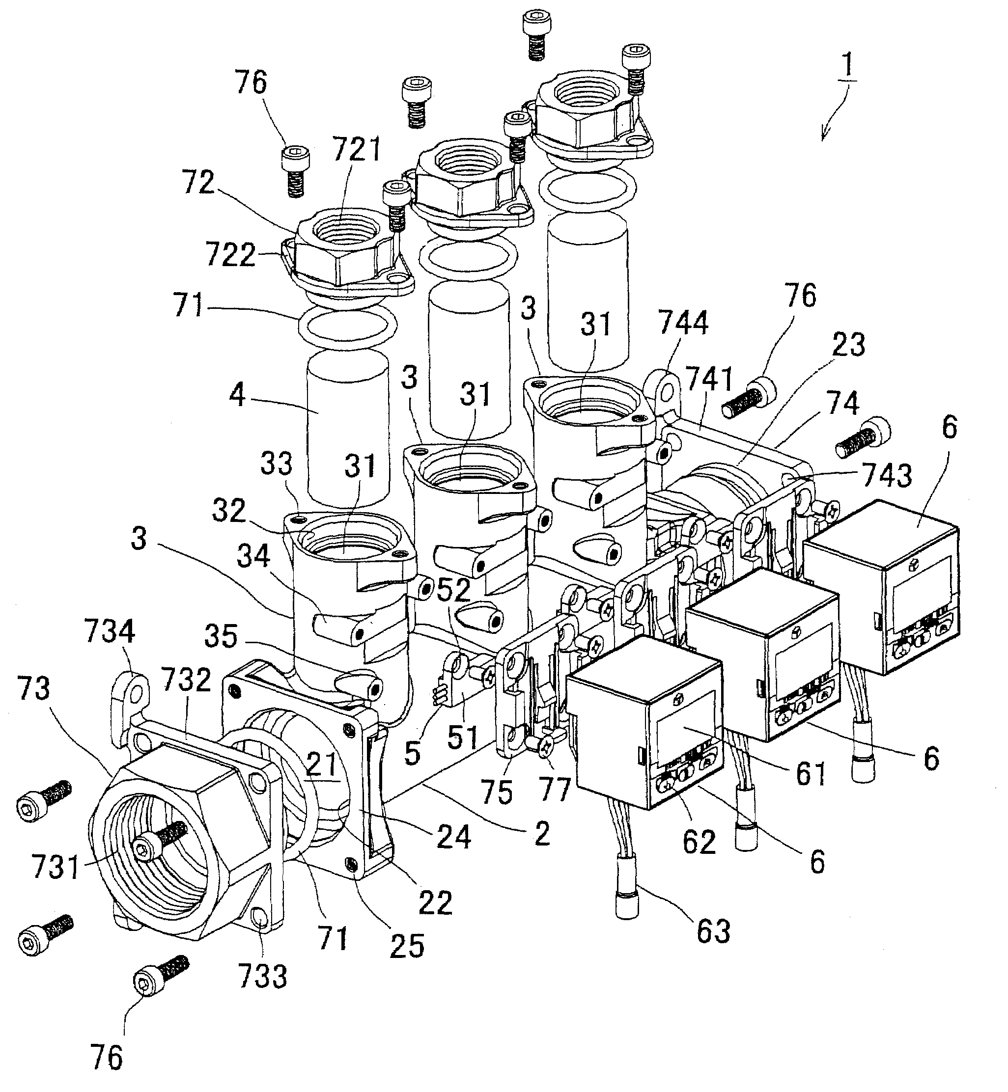
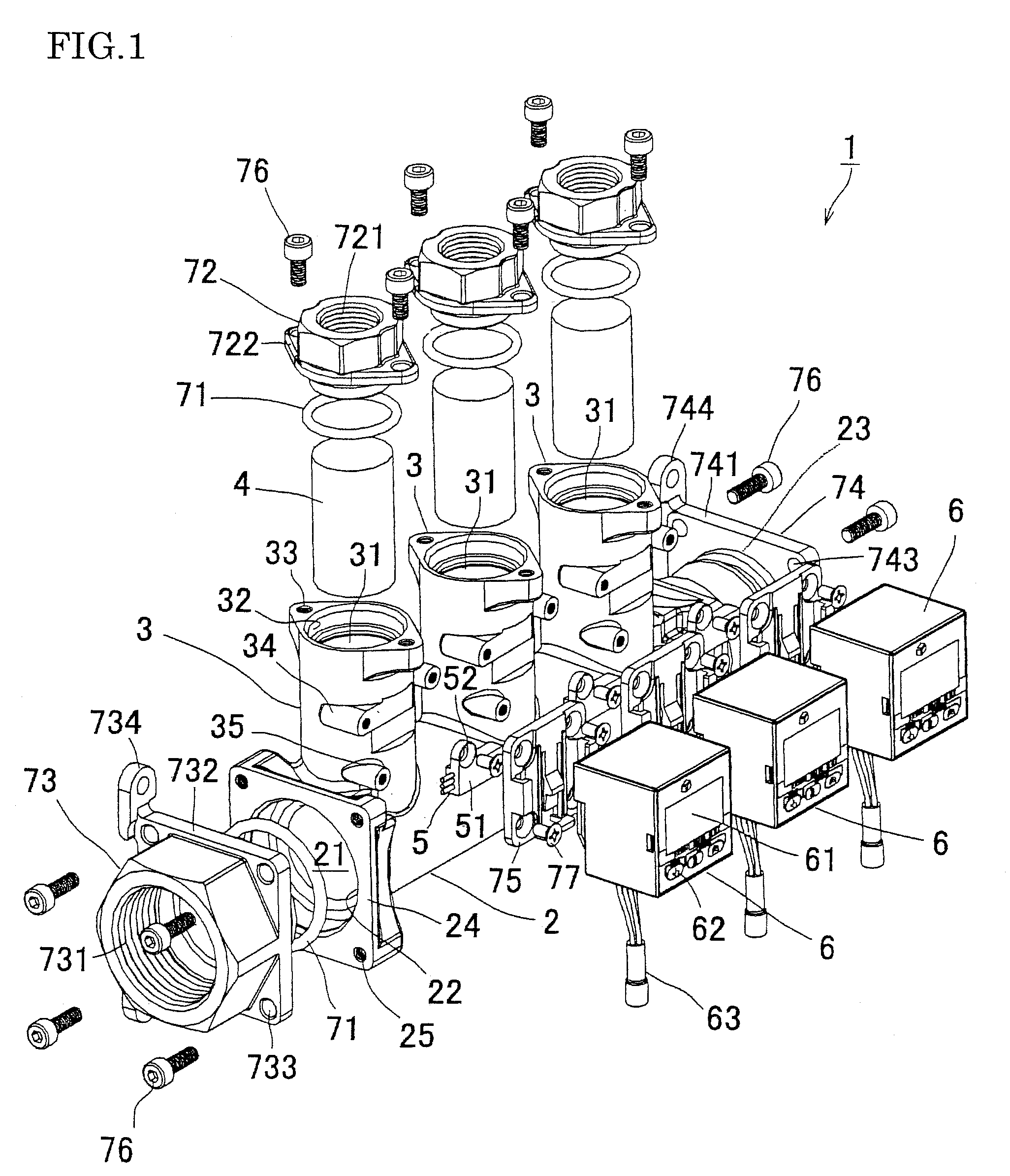
[0032]First, with reference to FIGS. 1 to 3, the basic construction of a pipe assembly unit with built-in flow sensors of this embodiment will be described. FIG. 1 is an exploded view showing the general construction of a pipe assembly unit with built-in flow sensors. FIG. 2 is an exploded sectional view showing the construction of a flow sensor in the unit. FIG. 3 is an assembled sectional view showing the internal construction of the unit.

[0033]A pipe assembly unit with built-in flow sensors (hereinafter abbreviated as a “pipe assembly unit”) 1 of this embodiment can be used, in its concrete applications, for example, as a water supply pipe for supplying water to a die apparatus (not shown) and a water discharge pipe, and the pipe assembly unit is characterized by the adoption of a manifold construction in which a main pipe 2 and branch pipes 3, 3, . . . which branch from the m...


PUM


Abstract

Cost is reduced by simplifying piping work and reducing the number of parts. At the same time, the degree of freedom in the arrangement of piping is raised by making the mounting posture of the piping variable. A pipe assembly unit with built-in sensors is fabricated by integrating a main pipe and multiple branch pipes, which branch from the main pipe and by building, in the multiple branch pipes a flow sensor which detects the flow rate of a fluid flowing through a conduit of each of the branch pipes, and the use of a conventional seal construction using a nipple in connections between the main pipe and the branch pipes is abolished. A pipe adapter having legs is detachably attached to opening ends of the main pipe and the legs are fixed to an installation surface A by changing the orientation of the pipe adapter, whereby the mounting posture of the pipe assembly unit is made variable.

Description

BACKGROUND OF THE INVENTION[0001]1. Field of the Invention[0002]The present invention relates to a pipe assembly unit with built-in flow sensors in which a main pipe and branch pipes are integrated.[0003]2. Description of the Related Art[0004]There has hitherto been known a piping construction in which a pipe assembly is formed by connecting a main pipe and branch pipes of multiple systems and a flow sensor is mounted to each of the multiple branch pipes, whereby the monitoring of flow rates is performed. In the case of a piping construction of this kind, it is necessary to perform the connection of the main pipe and the branch pipes and the connection of the branch pipes and the flow sensors for each number of the systems of the branch pipes. At present, therefore, workers are forced to perform troublesome piping work.[0005]In connecting these pipes, seal tape is wound around a nipple in order to prevent liquid leakage from a connection and sealing is performed by screwing the nipp...

Claims


Application Information

Patent Timeline
Patent Type & Authority Patents(United States)
IPC IPC(8): G01F15/00
CPCE03B7/09F16L41/03F24D3/1066F24D3/1075G01F1/115G01F5/00G01F15/14G01F15/185F24D2220/044
Inventor KAWAMOTO, TAKAHIROTAJIMA, TAKAYUKI
Owner TOFLO CORP
Why Eureka
Try Eureka