
Low frequency bilateral communication over distributed power lines

a technology of distributed power lines and low frequency, applied in the field of data communication, can solve the problems of affecting the service life of customers, affecting the service life of customers,

Inactive Publication Date: 2007-05-29
HUNT TECH INC
View PDF5 Cites 83 Cited by
  • Summary
  • Abstract
  • Description
  • Claims
  • Application Information

AI Technical Summary

Benefits of technology

"The present invention provides a system and method for full-duplex data communications between an electric power distribution station and a power consumer via the same power distribution line. This allows for the transmission of information signals simultaneously with the electrical power signal, enabling the power consumer to receive and use the information they need without the need for additional wiring. The invention also includes methods for transmitting information signals using a low-frequency modulating circuit and a signal transmission device that can alter the phase of the power signal to transmit information. The technical effects of the invention include improved efficiency and reliability in data communication, reduced costs, and improved safety and reliability in power distribution."

Problems solved by technology

For example, electric companies are migrating from costly and time-consuming manual methods of determining the amount of power consumed by customers of the power company.
This type of process was costly, slow, and intrusive to their customers.
While general information, such as the current price of power, price increases, etc. may be made available to customers via mail or telephone, it is again costly, time consuming, and intrusive.
Otherwise, the power company may have to purchase more expensive power from alternative sources to meet its peak load demand.
Furthermore, customers could also tamper with the pager systems to avoid having their power temporarily terminated, while continuing to obtain the cost discount.

Method used


Image

  • Low frequency bilateral communication over distributed power lines
  • Low frequency bilateral communication over distributed power lines
  • Low frequency bilateral communication over distributed power lines

Examples


Embodiment Construction

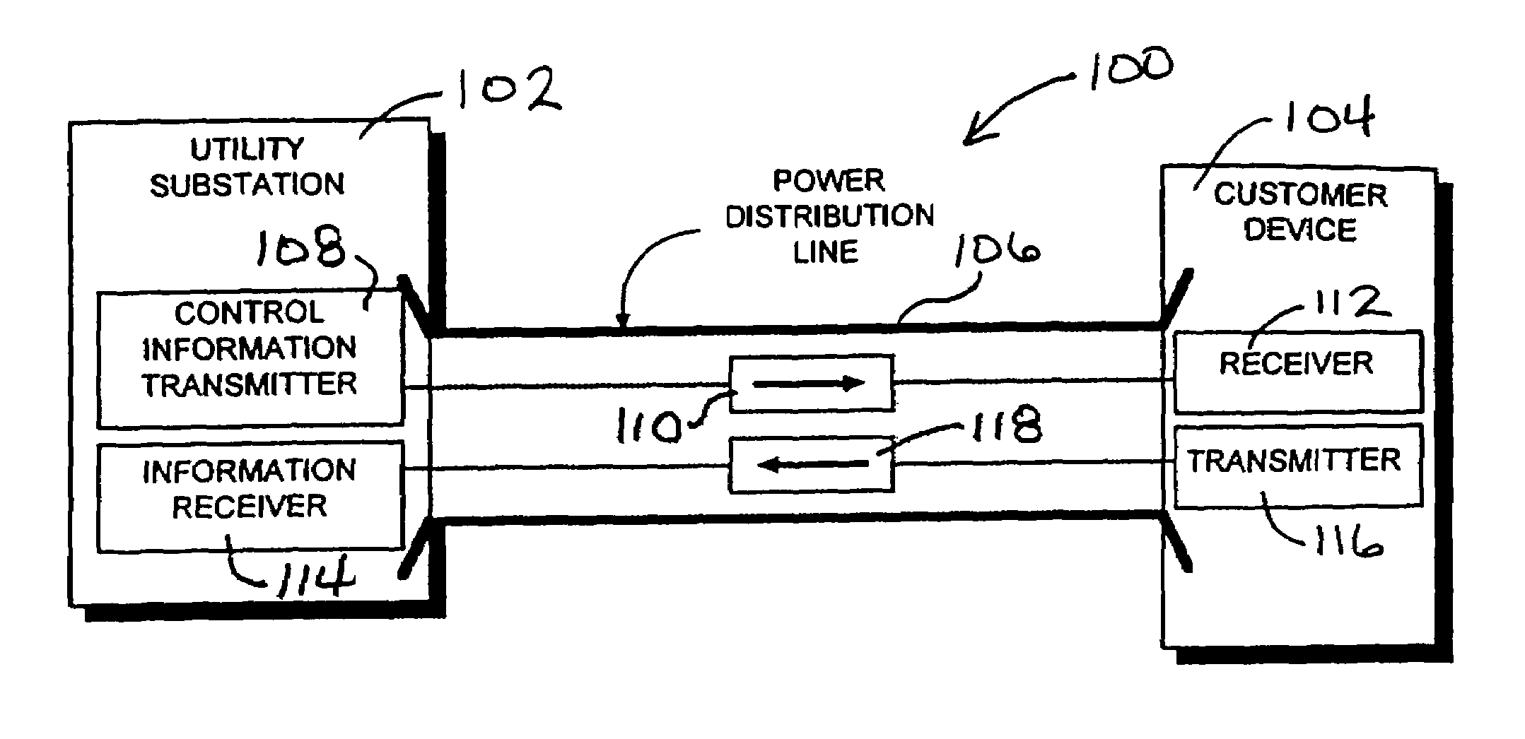
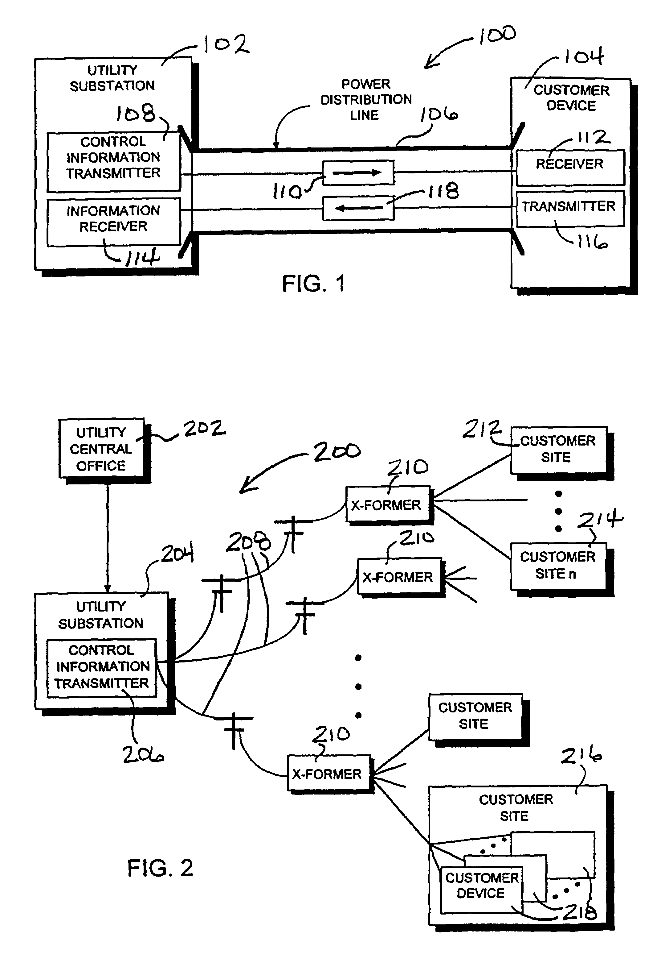
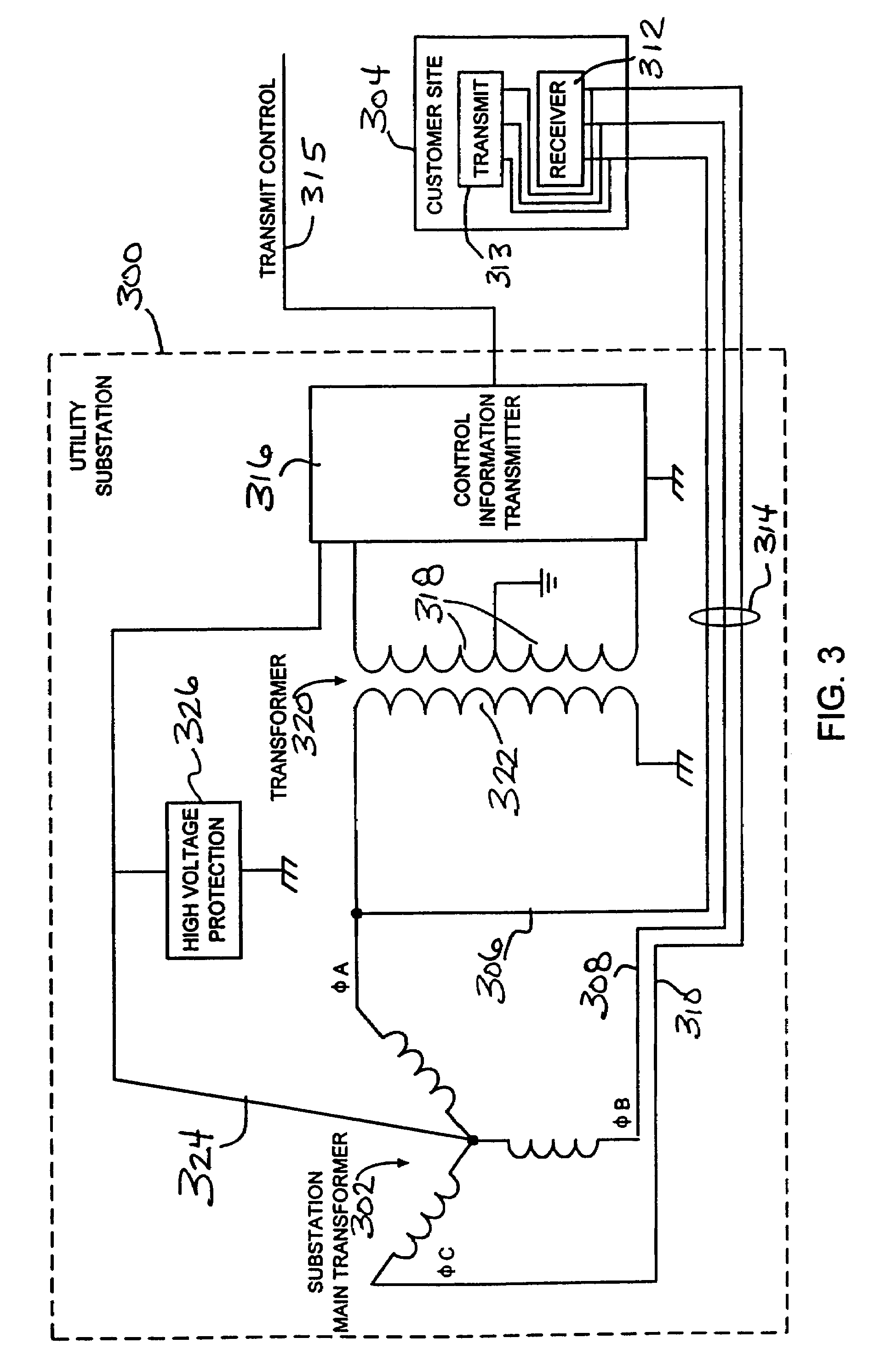
[0026]FIG. 1 is a block diagram of one link of an electric distribution system 100 distributing power between a utility substation and a customer device at the power consumer's site. An electric distribution system, or distribution plant as it is sometimes referred to, is all of that part of an electric power system between the bulk power source or sources and the consumer service switches. The bulk power sources are located in or near the load area to be served by the distribution system, and may be either generating stations or power substations supplied over transmission lines. Subtranmission circuits extend from the bulk power source or sources to the various distribution substations located in the load area The subtransmission circuits typically consist of underground cable, aerial cable, or overhead open-wire conductors carried on poles, or some combination of them.

[0027]Each distribution substation normally serves its own load area, which is a subdivision of the area served b...


PUM


Abstract

A system and method for providing full-duplex data communications between an electric power distribution station and a power consumer via the power distribution line providing electric power is provided. A first information transmitter, coupled to the power distribution circuit, provides first information signals concurrently with the power signal to the power consumer via the power distribution line. A first information receiver, coupled to a power consumer device powered by the electrical power signal, receives the first information signals via the electric power distribution line. A second information transmitter coupled to the power consumer device provides second information signals concurrently with the electrical power signal. A second information receiver, coupled to the power distribution circuit, receives the second information signals via the electric power distribution line. The information signals transmitted on the power distribution line can be transmitted at a frequency lower than the frequency of the transmitted power signal.

Description

RELATED APPLICATIONS[0001]This application is a continuation of application Ser. No. 10 / 649,061, filed Aug. 27, 2003, now abandoned which is a continuation of application Ser. No. 10 / 208,431, filed Jul. 29, 2002, now abandoned which is a continuation of application Ser. No. 09 / 723,090, filed Nov. 27, 2000, now abandoned which is a continuation of application Ser. No. 08 / 933,745, filed Sep. 23, 1997, now U.S. Pat. No. 6,154,488, which applications are incorporated herein.FIELD OF THE INVENTION[0002]This invention relates generally to data communications, and more particularly to a system and method for providing full-duplex data communications between an electric power distribution station and a power consumer, via the same power distribution line that provides electric power to the power consumer, at frequencies at or below the frequency of the electric power signal.BACKGROUND OF THE INVENTION[0003]As is true with most companies, utility companies are striving to reduce overhead cos...

Claims


Application Information

Patent Timeline
Patent Type & Authority Patents(United States)
IPC IPC(8): H04L27/00H04B1/38H02J7/00H02J13/00
CPCH02J13/0024H02J13/0051H04B3/54H04B2203/542H02J13/0001H02J13/00034Y04S10/52H02J13/00009
Inventor HUNT, PAUL C.
Owner HUNT TECH INC
Learn More