Liquid paint coater

Active Publication Date: 2007-05-29
SHINWA SEISAKUSHO CO LTD
View PDF12 Cites 9 Cited by
  • Summary
  • Abstract
  • Description
  • Claims
  • Application Information

AI Technical Summary

Benefits of technology

[0011]The stem of the stemmed brush has enhanced flexibility and better slidability in the axial direction against the wiper abutting against the stem, as compared with conventional wipers having no offset scraping section. This is because the inventive wiper includes at least one scraping section occupying a peripheral domain of the wiper is offset in the axial direction.
[0016]When the scraping sections of the wiper are in tight contact with the outer surface of the stem of the stemmed brush, the upper and lower spaces formed above and below the wiper, respectively, communicate with each other by the multiplicity of minute gaps (air passages) formed at substantially equal angular interval about the axis of the wiper in association with the multiple axially overlapping sections in tight contact with the stem. Thus, air can pass through the gaps quickly during insertion and withdrawal of the stemmed brush, creating no offset load of air pressure on either of the stemmed brush and the wiper.
[0019]As compared with conventional wipers having concentric scraping sections, the wiper of the present invention having a spiral scraping section provides enhanced flexibility to the scraping section abutting on the stem of the stemmed brush, thereby providing the stemmed brush with better slidability in the axial direction.
[0022]On the other hand, when the stemmed brush is withdrawn from the container, the scraping section of the wiper is in tight contact with the outer surface of the stem, thereby causing the scraping section to scrape off the cosmetic adhering to the stem. The gap, formed along the inner peripheral surface of the axially overlapping scraping portions of the wiper for escapement of the air in the container, extends in the peripheral (i.e. spiral) direction, in communication with the spaces above and below the wiper. However, the inner peripheral surface of the scraping section of the wiper is continuous in the peripheral (i.e. spiral) direction, so that the scraping section will not fail to scrape off the cosmetic adhering to the stem. When the stemmed brush is withdrawn from the container, the scraping section is in tight contact with the stem, but that (ambient) air can come into the container through the minute gap (air passage), so that the pressure in the container will never be negative and generate a resistive force acting on the withdrawing brush.

Problems solved by technology

On the other hand, when the stemmed brush 5 is withdrawn, the pressure in the container 2 becomes negative, which causes an adverse resistive force on the stemmed brush 5, thereby hindering easy withdrawal of the stemmed brush 5 from the container 2.
However, this second prior art configuration presents (FIG. 18) a problem that the slit 4a1 of the scraping section 4a leaves the cosmetic not scraped on the stem 5a.

Method used


Image

  • Liquid paint coater
  • Liquid paint coater
  • Liquid paint coater

Examples


first embodiment

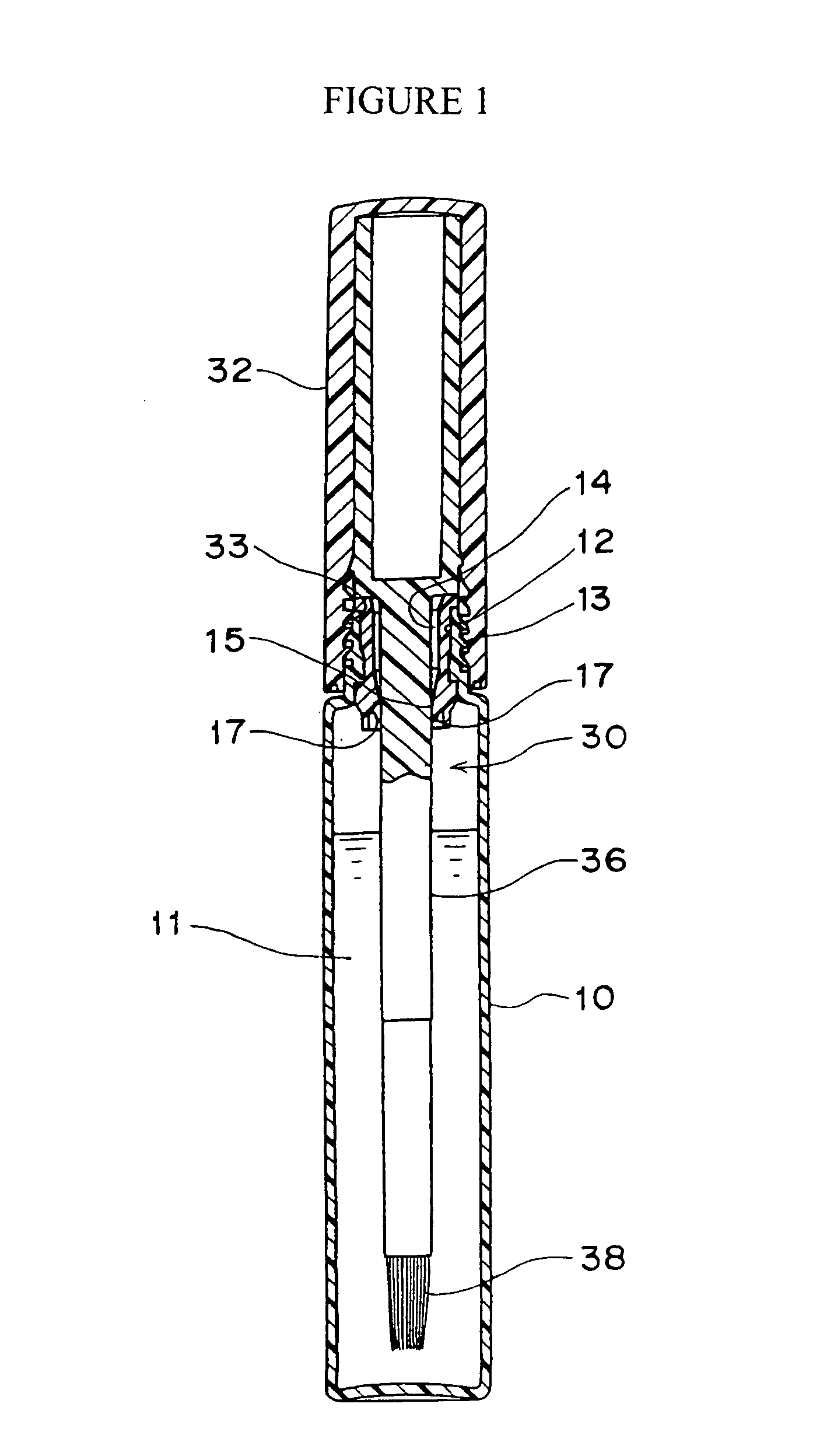
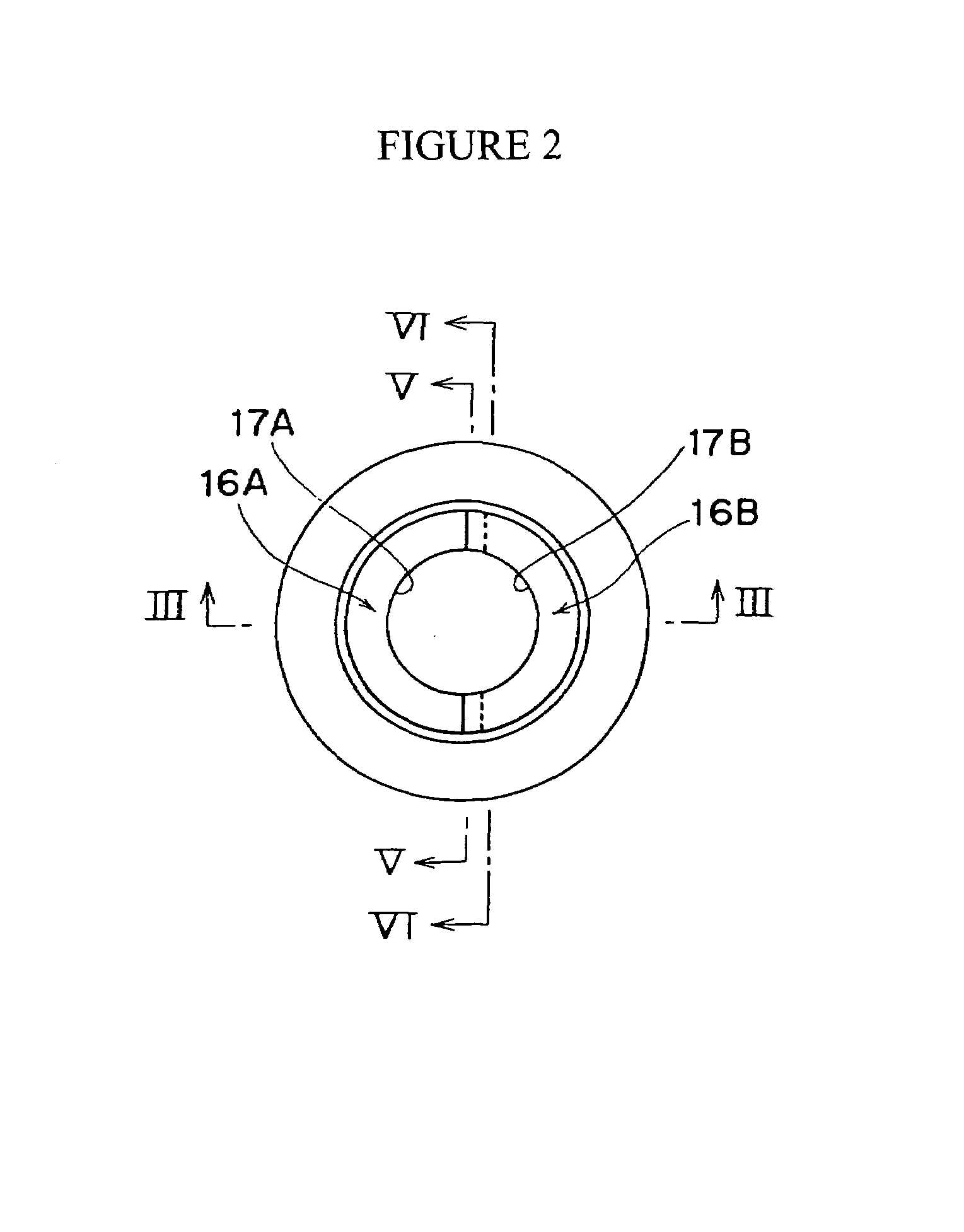
[0042]FIGS. 1–10 show the invention as defined in claim 1. More specifically, FIG. 1 is a longitudinal cross sectional view of a liquid-cosmetic applicator in accordance with one embodiment of the invention. FIG. 2 is an enlarged plan view of a wiper of the cosmetic applicator of FIG. 1. FIG. 3(a) is an enlarged longitudinal cross sectional view of the wiper, and FIG. 3(b) is a diagram illustrating the shape of the wiper. FIG. 4 is an enlarged bottom view of the wiper. FIG. 5 is an enlarged longitudinal cross sectional view of the axially overlapping scraping sections the wiper taken along line V—V of FIG. 2 and FIG. 3(a). FIG. 6 is another enlarged longitudinal cross sectional view of the axially overlapping scraping sections of the wiper taken along line V—V of FIG. 2 and FIG. 3(b). FIG. 7 is a still enlarged cross sectional view of the axially overlapping scraping sections. FIG. 8 is a cross sectional view of a minute gap (air passage) formed between the external surface of the s...

second embodiment

[0051]Referring to FIGS. 11 and 12, there is shown a liquid-cosmetic applicator according to the invention. FIG. 11 is an enlarged plan view of the wiper which is a main portion of the liquid-cosmetic applicator. FIG. 12 is a longitudinal cross sectional view of the wiper taken along line XH—XH of FIG. 11.

[0052]Like the first embodiment having the scraping sections 17A and 17B, the leading end of the tapered cylindrical wiper of the second embodiment has an inner diameter D and is divided into a first through a third wiper domains 16C–16E each occupying a substantially ⅓ peripheral domain of the tapered end of the wiper. They are sequentially offset by a distance d in the axial direction, as shown in FIG. 3(b). Each of the lowest (first) wiper domain 16C, the middle (second) wiper domain 16D, and the uppermost (third) wiper domain 16E has an edge section integral with the one neighboring in the peripheral direction. These edge sections will be referred to as joint sections. Each of ...

third embodiment

[0054]Referring to FIGS. 13 and 14, there is shown a liquid-cosmetic applicator according to the invention. FIG. 13 is an enlarged plan view of a wiper of the liquid-cosmetic applicator. FIG. 14 is a longitudinal cross sectional view of the wiper taken along line XIV—XIV of FIG. 13.

[0055]Like the scraping sections 17A and 17B of the first embodiment, the leading end of the tapered cylindrical wiper of the third embodiment has an inner diameter D and is angularly divided into four regions occupying substantially equal peripheral domains of the wiper (the regions referred to as peripheral regions) in such a way that they are alternately offset in the axial direction by a distance d as shown in FIG. 3(b), and each integrally joined at the opposite edged thereof with neighboring ones in the peripheral direction, forming joint sections. In these joint sections, the scraping sections of the neighboring wiper domains overlap each other in the axial direction. Four gaps are formed along the...


PUM


Abstract

A liquid-cosmetic applicator is provided having a wiper formed on the inside of an elongated opening of a liquid-cosmetic container for scraping off the liquid cosmetic that adheres to the stem of a stemmed brush. The wiper includes at least two wiper domains that overlap along the longitudinal axis of said opening, each domain having a scraping section at one axial end, and a non-scraping section at an opposite end, the scraping sections being axially offset from one another and having sides that mutually engage along at least one interface. The interface provides a gap between said stem when said stem of said brush engages said scraping sections of said wiper domains that in turn defines an air passage that allows air to axially flow through said wiper as said stem is being wiped thereby eliminating unwanted suction forces when the applicator is withdrawn from the container.

Description

FIELD OF THE INVENTION[0001]The invention relates to a liquid-cosmetic applicator such as a lip gross applicator and a mascara applicator, and more particularly to a liquid-cosmetic applicator having a wiper for scraping off the cosmetic that adheres to the stem of the applicator, the wiper formed inside an opening section of a liquid-cosmetic container for inserting the stemmed brush.BACKGROUND OF THE INVENTION[0002]As shown in FIG. 17, this type of liquid cosmetic applicator comprises a container 2 containing therein liquid cosmetic 1 and a stemmed brush 5 which has a cap 6 that can be fitted on an opening 3 of the container 2. Mounted on the outer periphery of the opening 3 of the container 2 is a wiper 4 formed of a flexible material such as a resin or rubber. The wiper 4 has a scraping section 4a adapted to scrape the cosmetic adhering to the stem 5a of the stemmed brush 5 off the stem 5a as the stemmed brush 5 is withdrawn out of (the opening 3) of the container 2. Portion 5b ...

Claims


Application Information

Patent Timeline
IPC IPC(8): A46B11/00A45D34/04B65D39/04B65D51/32
CPCA45D34/04A45D34/046
Inventor HIYAMA, HIROSHI
Owner SHINWA SEISAKUSHO CO LTD
Why Eureka
Try Eureka