


Quick Research
Generate reliable direction feasibility study reports for your R&D in just a few steps.

Technical Q&A
Discover and master advanced knowledge NOW. Basics, ideas, possibilities, all at once.

Find Solutions
As an expert in R&D theories, this can generate solutions to your technical problems instantly.

Evaluate Feasibility
Analyze your overall solution with one click, know your potential R&D risks in advance.

Monitor Landscape
Get weekly tech updates, stay abreast of the latest tech innovations and key insights.
Impact test apparatus and impact test method
a test apparatus and test method technology, applied in the direction of instruments, fluid tightness measurement, structural/machine measurement, etc., can solve the problems of difficult to evaluate the stress-strain characteristic of the test piece, the difficulty of evaluating the impact force applied to the test piece, and the difficulty of evaluating the impact absorbing material
- Summary
- Abstract
- Description
- Claims
- Application Information
AI Technical Summary
Benefits of technology
Problems solved by technology
Method used
Image


Examples
embodiment 1
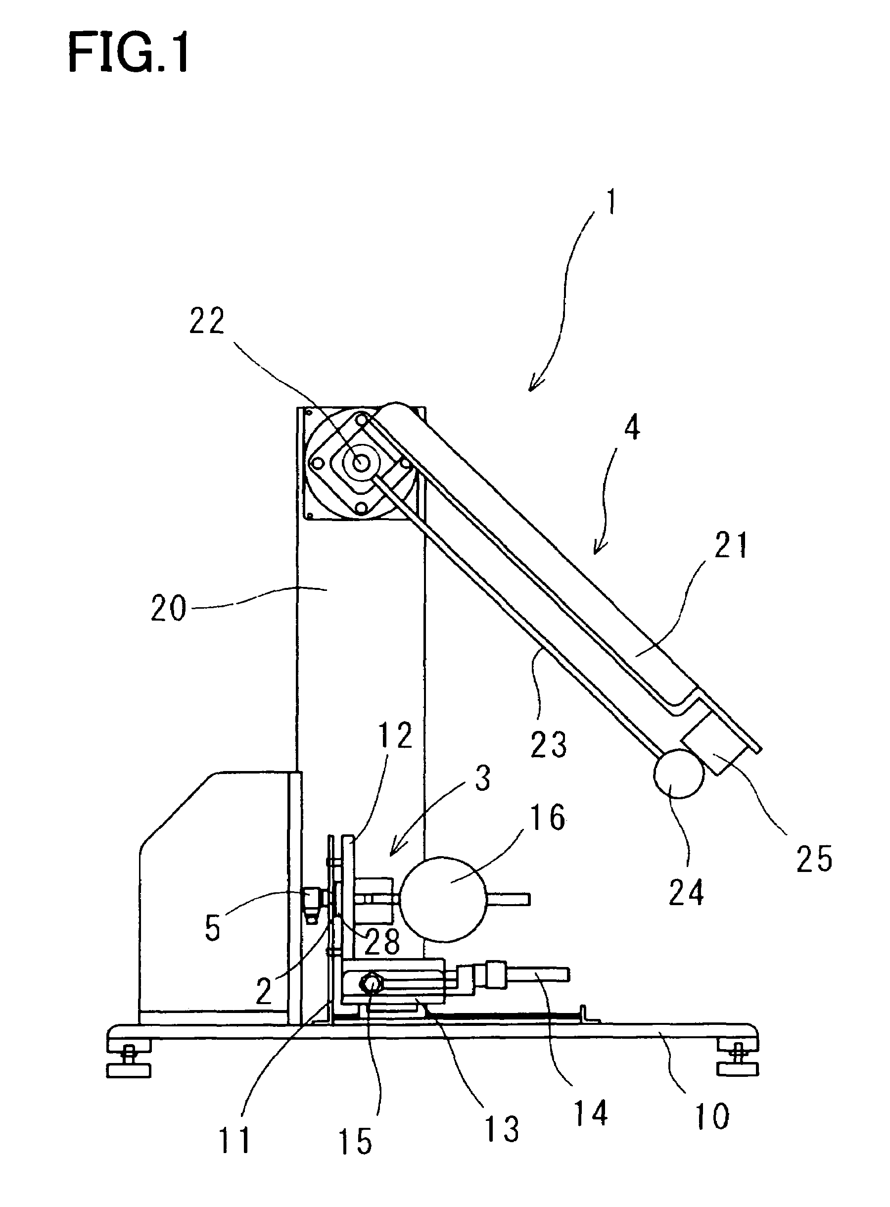
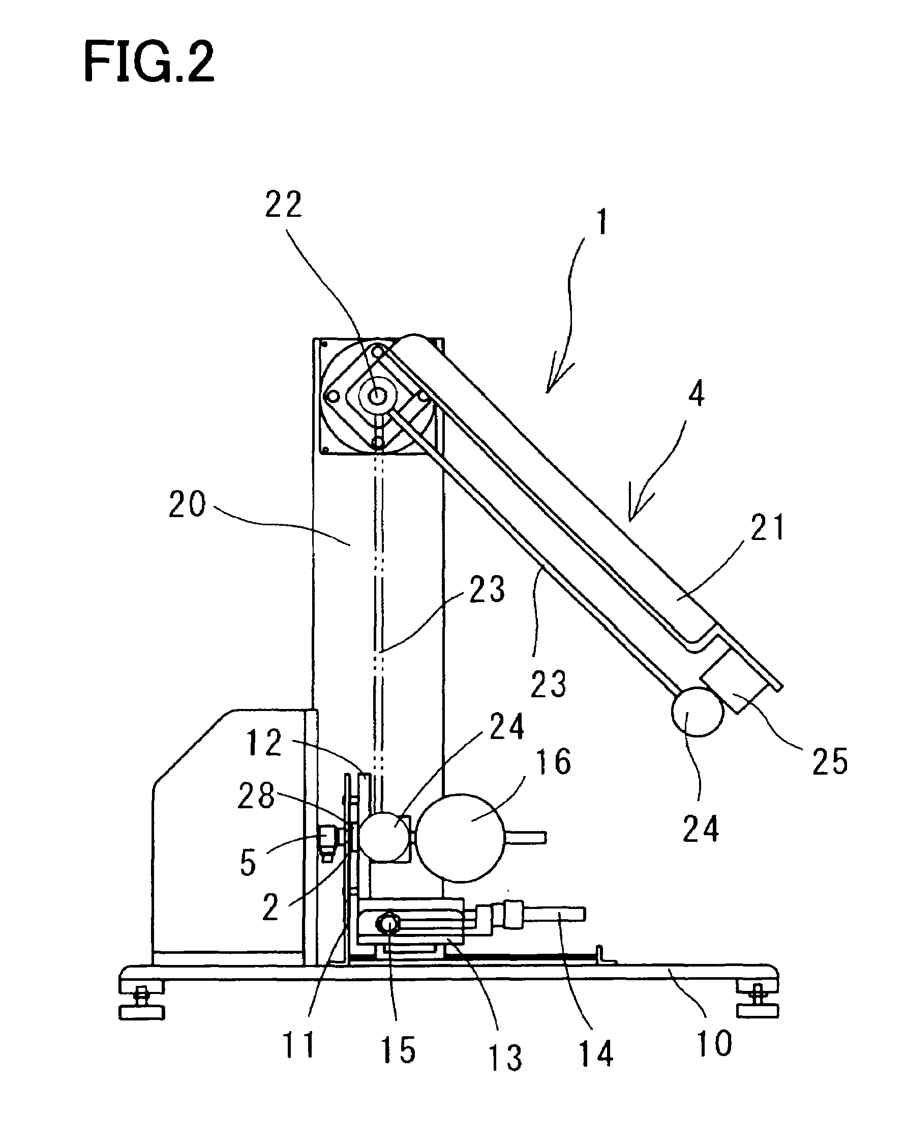
[0028]First, the schematic construction of an impact test apparatus in a first will be described with reference to FIGS. 1 to 4.
[0029]As shown in FIGS. 1 to 4, an impact test apparatus 1 in the first embodiment is constructed of: a holding device 3 for holding a test piece 2 at an arbitrary force; an impact applying device 4 for applying an impact stress to the test piece 2; a force sensor 5 as an impact force sensing device for sensing an impact force applied to the test piece 2 by the impact applying device 4; a high-speed camera 6 as a displacement detecting device for detecting the displacement of the test piece when the impact applying device 4 applies an impact force to the test piece 2; and an output device 7 for synchronizing a signal from the force sensor 5 with a signal from the high-speed camera 6 and outputting an impact stress-strain characteristic curve as impact stress-strain characteristic information expressing the relationship between an impact stress of the test p...
embodiment 2
[0054]Next, the schematic construction of an impact test apparatus in a second embodiment will be described with reference to FIGS. 7 to 9. Here, in the following description, the same reference symbols as in the construction or the like of the impact test apparatus 1 in the first embodiment shown in FIGS. 1 to 4 denote the same or equivalent parts as in the construction or the like of the impact test apparatus 1 in the first embodiment.
[0055]The schematic construction and control construction of an impact test apparatus in the second embodiment are nearly equal to those of the impact test apparatus 1 in the first embodiment.
[0056]However, as shown in FIGS. 7 to 9, an impact test apparatus 51 in the second embodiment is different from the construction of the impact test apparatus 1 in the first embodiment in that the holding device 3 having the force sensor 5 fixed thereto and the impact applying device 4, which construct the impact test apparatus 1 in the first embodiment, are disp...
embodiment 3
[0085]As shown in FIG. 11, in place of measuring the displacement of the test piece 2 by the use of the above-described high-speed camera 6, for example, an acceleration sensor 81 is fixed in a position close to a portion where the hammer 24 is brought into collision with the supporting plate 28 and an acceleration when the hammer 24 is brought into collision with the supporting plate 28 is integrated twice. With this, the displacement of the test piece 2 can be also found.
PUM
| Property | Measurement | Unit |
|---|---|---|
| humidity | aaaaa | aaaaa |
| temperatures | aaaaa | aaaaa |
| temperatures | aaaaa | aaaaa |
Abstract
Description
Claims
Application Information
 - R&D Engineer
- R&D Manager
- IP Professional
- Industry Leading Data Capabilities
- Powerful AI technology
- Patent DNA Extraction
Browse by: Latest US Patents, China's latest patents, Technical Efficacy Thesaurus, Application Domain, Technology Topic, Popular Technical Reports.
© 2024 PatSnap. All rights reserved.Legal|Privacy policy|Modern Slavery Act Transparency Statement|Sitemap|About US| Contact US: help@patsnap.com