
Image forming apparatus which prevents misregistration

a technology forming apparatus, which is applied in the field of image forming apparatus, can solve problems such as misregistration, and achieve the effect of preventing misregistration

Inactive Publication Date: 2007-05-22
CANON KK
View PDF18 Cites 6 Cited by
  • Summary
  • Abstract
  • Description
  • Claims
  • Application Information

AI Technical Summary

Benefits of technology

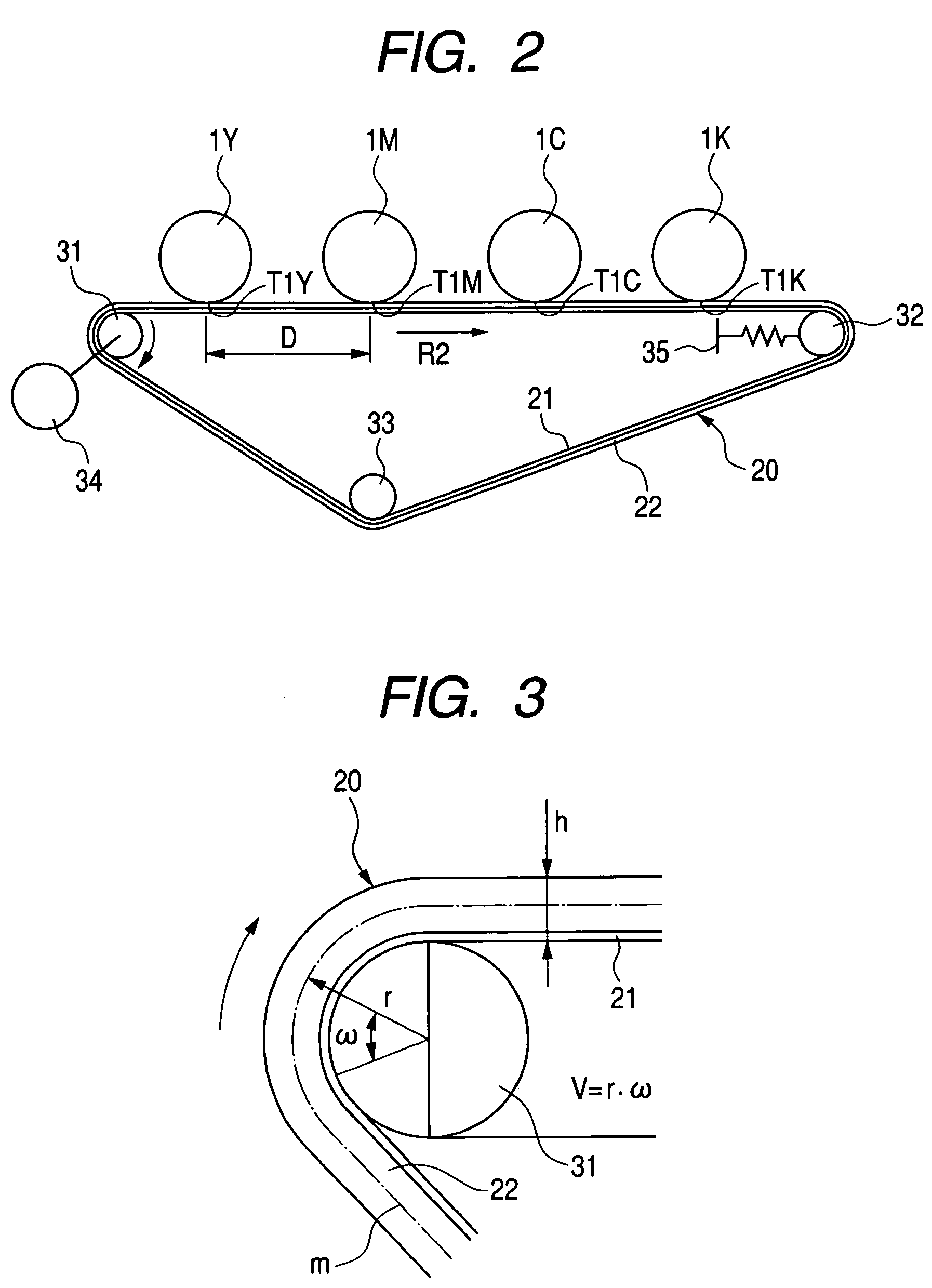
The present invention relates to an image forming apparatus that can prevent misregistration in images formed by toner images being superimposed on an intermediate transferring member, recording material born by a recording material bearing member or electrostatic image bearing member. The invention achieves this by providing an image forming apparatus comprising a first image bearing member, first toner image forming means, an intermediate transferring member, a first primary transfer region, a second image bearing member, second toner image forming means, and a second primary transfer region. The distance between the central position of the first primary transfer region and the central position of the second primary transfer region is approximately integer multiples of the predetermined interval. This ensures that the toner images formed on the first and second image bearing members are transferred to the intermediate transferring member in a precise manner, thereby preventing misregistration.

Problems solved by technology

However, when using the belt-shaped intermediate transferring member, recording material bearing member or electrostatic image bearing member, a toner image is not formed on a desired position of the intermediate transferring member, recording material born by a recording member or electrostatic image bearing member manufactured by the above-described method and a problem occurs that the so-called misregistration occurs because a relative position of each toner image follows a desired position.

Method used


Image

  • Image forming apparatus which prevents misregistration
  • Image forming apparatus which prevents misregistration
  • Image forming apparatus which prevents misregistration

Examples


Embodiment Construction

[0027]According to the study by the present inventor, periodic thickness unevenness occurs in the intermediate transferring member in the manufacturing steps of the intermediate transferring member, recording material bearing member and electrostatic image bearing member.

[0028]Moreover, the running speed of the intermediate transferring member is periodically changed due to the periodic thickness unevenness. The periodic speed change is a cause of misregistration.

[0029]Therefore, in the case of the present invention, the above problem is solved by setting the distance between primary transfer portions in which a toner image on an image bearing member is transferred to an intermediate transferring member, the distance between transfer portions in which a toner image on an image bearing member is transferred to a recording material borne by and conveyed to a recording material bearing member and the distance between forming regions in which an electrostatic image is formed on an elect...


PUM


Abstract

To provide an image forming apparatus including a first image bearing member, first toner image forming means which forms a first toner image on the first image bearing member, an intermediate transfer member in which a circumferential face is formed, the circumferential face rotates in a predetermined direction by using the center of the circumferential face as a rotating center and the thickness is periodically changed at a predetermined interval in the predetermined rotating direction, a first primary transfer region in which the first toner image on the first image bearing member is transferred to the intermediate transfer member, a second image bearing member and a second primary transfer region in which the toner image on the second image bearing member is transferred to the intermediate transfer member to which the first toner image is transferred, in which the distance between the central position of the first primary transfer region and the central position of the second primary transfer region in the rotating direction of the intermediate transfer member is approximately integer times of the predetermined interval. Thereby, it is possible to restrain misregistration from occurring.

Description

BACKGROUND OF THE INVENTION[0001]1. Field of the Invention[0002]The present invention relates to an image forming apparatus for preventing misregistration from occurring due to a change of thicknesses of an intermediate transferring member in a color image forming apparatus using the intermediate transferring member whose thicknesses are periodically varied, a recording material bearing member and an electrostatic image bearing member.[0003]2. Related Background Art[0004]In the case of an image forming apparatus using the electrophotography, a color image forming apparatus capable of forming a color image has been popular with users.[0005]In the case of an electrophotographic color image forming apparatus, the following systems are used: a system for superimposing a plurality of toner images on an intermediate transferring member, a system for superimposing a plurality of toner images on a recording material born by a recording material bearing member and a system for superimposing ...

Claims


Application Information

Patent Timeline
Patent Type & Authority Patents(United States)
IPC IPC(8): G03G15/01G03G15/16G03G15/00
CPCG03G15/0189G03G15/1615G03G2215/0129G03G2215/0141G03G2215/0158
Inventor KISHI, TAKEHIRO
Owner CANON KK
Learn More