
Cover for multiplex receptacle set

Inactive Publication Date: 2007-05-22
TA HSING ELECTRIC WIRE & CABLE
View PDF7 Cites 19 Cited by
  • Summary
  • Abstract
  • Description
  • Claims
  • Application Information

AI Technical Summary

Benefits of technology

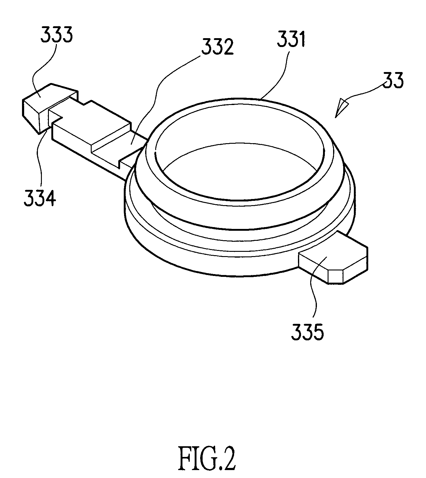
[0010]In view of the above defects of the conventional techniques, the structure for connecting a plurality of covers with the main body is redesigned in the present invention. In the present invention, each of a plurality of receptacles of a multiplex and multi-directional receptacle set is provided on a lateral side thereof with an insertion socket formed integrally therewith and having a through hole; the covers are openably and closably provided on the receptacles and each has a bent strip extended laterally thereof; the bent strip has a conical engaging block on its tailing end. All the engaging blocks are used to be directly engaged in the through holes of the insertion sockets to form connection; so that the covers are kept at the sockets to be opened or closed relative to the sockets. Thereby, the covers are easily and firmly assembled at the sockets to be convenient for operation of a user to open or close, and an effect of saving material can be obtained.

Problems solved by technology

This can get a one-for-plural effect, however, the receptacles are closely arranged along straight lines, plugs are very hard to be plugged in or extracted.
By the fact that the receptacles themselves have sizes of a predetermined specification, the annular mounting portions each must be made with quite a large size to be engaged in a mounting groove, hence material is wasted quite much.
Besides, the connecting action for engaging an annular mounting portion in a mounting groove is harder; particularly the annular mounting portion is subjected to be broken by stretching and thereby is no more useful, or the annular mounting portion which surrounds a receptacle is subjected to being worn out and broken after use for a long time.
It is very difficult in assembling to fix by using the screws or the appropriate pressing member, this will largely increase the working hours in manufacturing a receptacle set, and also increase the cost of manufacturing.

Method used


Image

  • Cover for multiplex receptacle set
  • Cover for multiplex receptacle set
  • Cover for multiplex receptacle set

Examples


Embodiment Construction

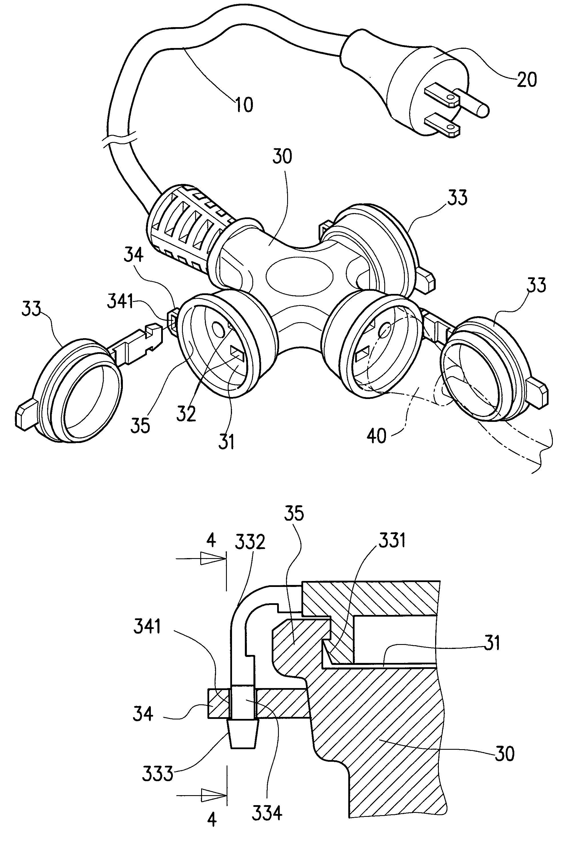
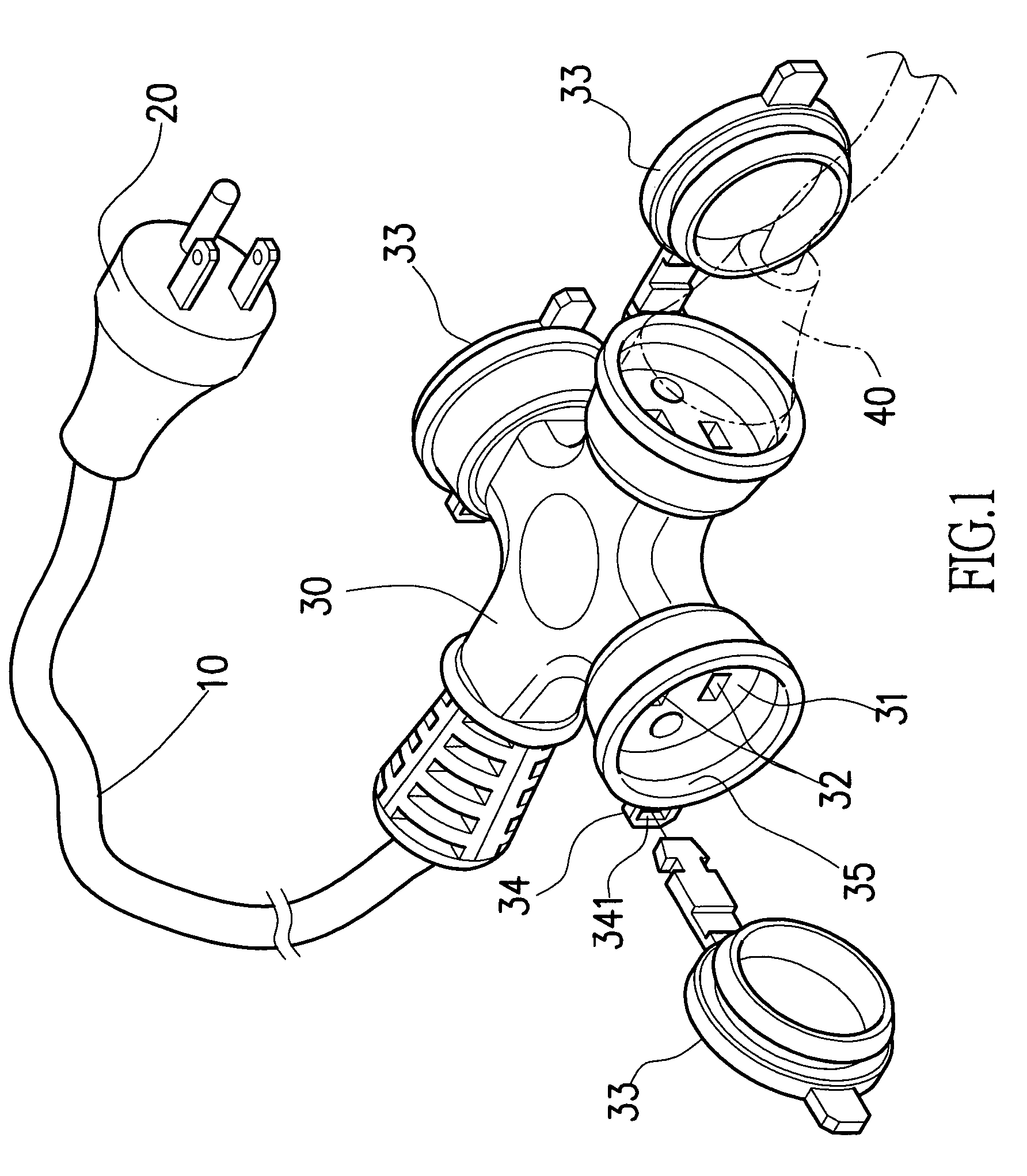
[0018]Referring to FIG. 1, a multiplex and multi-directional receptacle set for the present invention has an extension line 10 of which one end is a plug 20 that can be connected to an electric power supply, and of which the other end is connected to a main body 30 of the multi-directional receptacle set. The main body 30 of the multi-directional receptacle set as shown in the embodiment of FIG. 1 has three receptacles 31 in different orientations in a horizontal plane.

[0019]Insertion holes 32 of each receptacle 31 can be closed by covering of a cover 33 of the present invention, such as is shown in FIG. 1, in order to get an effect of dust and water proofing.

[0020]The cover 33 can also be opened away from the receptacle 31, so that the insertion holes 32 can be inserted therein with a plug 40, such as is shown in FIG. 1, in order to make electric connection.

[0021]A lateral side of each receptacle 31 formed on the main body 30 has an insertion socket 34 (having a through hole 341) e...


PUM


Abstract

A cover for a multiplex and multi-directional receptacle set in which each of a plurality of receptacles is provided on a lateral side thereof with an insertion socket formed integrally therewith and having a through hole; a plurality of covers same as the said cover can cover the receptacles and each has a bent strip extended laterally thereof; the bent strip has a conical engaging block on its tailing end. The engaging blocks are used to be directly engaged in the through holes of the insertion sockets to form connection; so that the covers are kept at the sockets to be opened or closed relative to the sockets. Thereby, the covers are easily and firmly assembled at the sockets to be convenient for operation of a user to open or close, and an effect of saving material can be obtained.

Description

BACKGROUND OF THE INVENTION[0001]1. Field of the Invention[0002]The present invention is related to a cover for a multiplex and multi-directional receptacle set, and especially to a brand-new structure of a cover that can be connected by inserting an engaging block on a tailing end of a bent strip into a through hole provided on an insertion socket integrally formed on each of the receptacles on a main body of the multiplex and multi-directional receptacle set.[0003]2. Description of the Prior Art[0004]Generally, a conventional one-for-plural receptacle set was designed to be of the style with one or two sides, i.e., a plug on the tailing end of an electric line was connected with an elongate rectangular box on one or two sides of which plural receptacles were arranged linearly. This can get a one-for-plural effect, however, the receptacles are closely arranged along straight lines, plugs are very hard to be plugged in or extracted.[0005]Afterwards, a multiplex and multi-directional...

Claims


Application Information

Patent Timeline
IPC IPC(8): H01R13/44
CPCH01R13/447H01R13/501H01R13/506H01R13/5213H01R13/652H01R24/22H01R25/003H01R2103/00
Inventor LIU, WEI HO
Owner TA HSING ELECTRIC WIRE & CABLE
Learn More