Motor

a motor and motor body technology, applied in the field of motors, can solve the problems of increasing torque, increasing weight, and reducing torque in comparison with the theoretical value, so as to reduce the space factor of the coil, suppress the heat generation of the connected portion, and alleviate the effect of overloading magnetic saturation

Inactive Publication Date: 2007-05-15
PANASONIC CORP
View PDF16 Cites 17 Cited by
  • Summary
  • Abstract
  • Description
  • Claims
  • Application Information

AI Technical Summary

Benefits of technology

[0019]The present invention has been devised to solve the above-mentioned problems, and its objective is to provide a motor which can prevent the occurrence of a torque reduction even at the time of overloading, can immediately reduce the temperature of the motor main body upon an increase in the temperature of the motor main body, and has a high torque with a superior heat radiating property.
[0020]In a first aspect of the present invention, there is provided a motor comprising: a stator that is constituted by a stator main body having a plurality of slots formed on the circumference of a main body with equal intervals from each other and teeth each of which is located between the slots, and extends outward along the radial direction from the slot bottom face with the same width, and a coil bobbin that is attached to each of the teeth of the stator main body, and is formed by winding a wire around a bobbin that has been preliminarily made from an insulating material such as a resin, in a concentrated winding system; and a rotor that has a gear shape and is maintained on the circumference of the stator concentrically with the stator main body, in a manner so as to face the stator through a predetermined air gap. With this arrangement, it becomes possible to improve the space factor of the coil, and also to alleviate magnetic saturation in the overload.
[0021]In a second aspect of the present invention, there is provided a motor comprising: a stator that is constituted by a stator main body having a plurality of slots formed on the circumference of a main body with equal intervals from each other and teeth each of which is located between the slots, and extends outward along the radial direction from the slot bottom face with the same width, and a coil bobbin that is attached to each of the teeth of the stator main body, and is formed by winding a wire around a bobbin that has been preliminarily made from an insulating material such as a resin, in a concentrated winding system; and an embedding magnet type rotor that has a permanent magnet embedded therein, and is maintained on the circumference of the stator concentrically with the stator main body, in a manner so as to face the stator through a predetermined air gap. With this arrangement, it becomes possible to improve the space factor of the coil, and also to alleviate magnetic saturation in the overload.

Problems solved by technology

However, in the above-mentioned conventional reluctance motor, as the current increases, the torque increasing rate becomes lower, with the result that the torque decreases in comparison with the theoretical value.
Therefore, with respect to motors to be used with short-time rating, for example, those used in ABS devices and the like, in the case of the motor that causes a torque reduction when an attempt is made to obtain a predetermined torque, it is necessary to increase the thickness of laminated layers or the like, and this causes an increase in the weight, and the subsequent increase in the weight of the automobile or the like to carry the motor.
Moreover, the motor has an abrupt temperature rise due to use with short-time rating, resulting in degradation in reliability of insulating materials and the like.

Method used


Image

  • Motor
  • Motor
  • Motor

Examples


Embodiment Construction

[0040]Referring to attached drawings, the following description discusses embodiments of the present invention. Here, the following embodiments are merely examples which materialize this invention, and these do not limit the technical range of this invention.

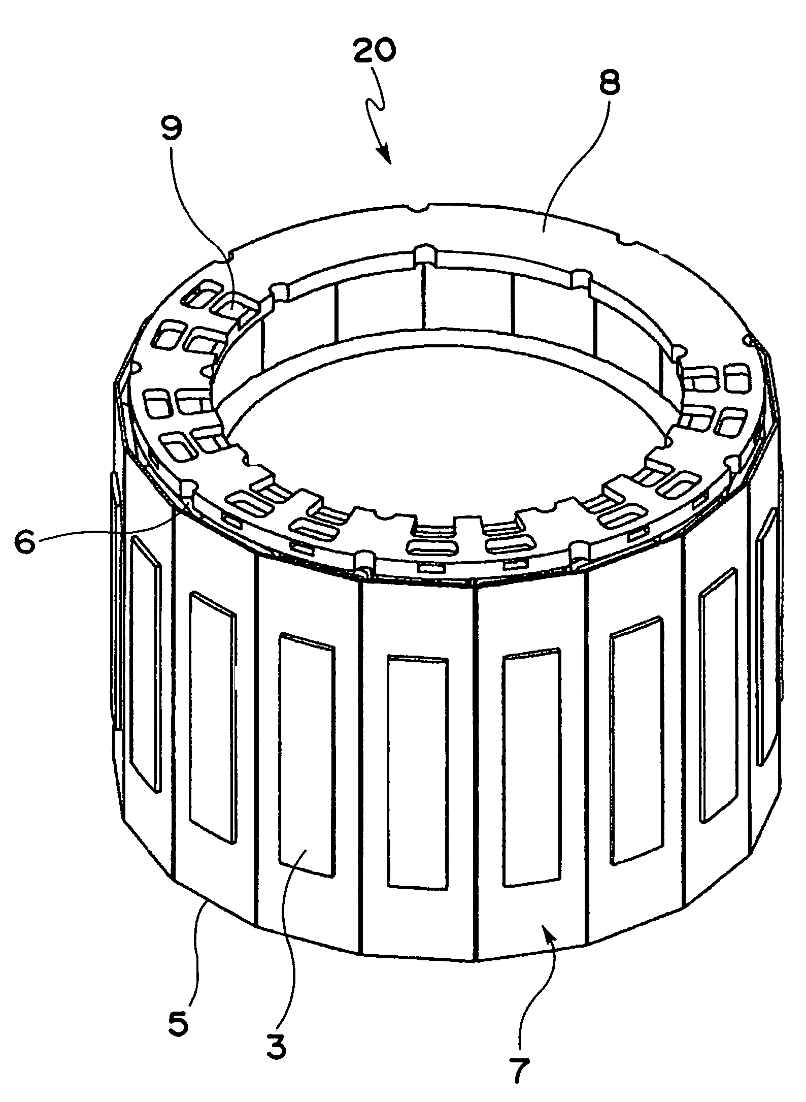
[0041]FIG. 1 shows a stator of the present invention, and in this Figure, reference numeral 3 is a tooth, 5 is a bobbin, 6 is a wire, 7 is a coil bobbin, 8 is a connection-use end plate, 9 is a conductor plate and 20 is a stator.

[0042]As shown in FIG. 2, the bobbins 5 are attached to a stator main body 1 (see FIG. 4) in the radial direction thereof, and each of the bobbins 5 is constituted by an end face wall 5a that defines both of the end faces in the radial direction and prevents overflow (protrusion toward the stator outer diameter side) of the wire 6 when wound around it, a winding portion 5b on which the wire 6 is wound and an attaching hole 5c that allows the attachment to tooth 3 (see FIG. 2).

[0043]FIG. 3 shows a coil bo...


PUM


Abstract

The objective of this invention is to provide a motor which can reduce occurrence of a torque reduction in the overload, and also lower the temperature of a motor main body immediately even in the case of a temperature rise in the motor main body.This motor comprises: a stator 20 that is constituted by a stator main body 1 having a plurality of slots 4 formed on the circumference of the main body with equal intervals from each other and teeth 3 each of which is located between the slots 4, and extends outward along the radial direction from the slot bottom face of the slots 4 with the same width, and a coil bobbin 7 that is attached to each of the teeth 3 of the stator main body 1, and is formed by winding a wire 6 around a bobbin 5 that has been preliminarily made from an insulating material such as a resin, in a concentrated winding system; and a rotor 2 that is maintained on the circumference of the stator 20 concentrically with the stator main body 1, in a manner so as to face the stator main body 1 through a predetermined air gap 19.

Description

[0001]This Application is a U.S. National Phase Application of PCT International Application PCT / JP02 / 11664 filed on Nov. 8, 2002.TECHNICAL FIELD[0002]The present invention relates to a motor that is used with short-time rating.BACKGROUND ART[0003]FIG. 10 shows a stator structure that is incorporated in a conventional motor, and in this Figure, reference numeral 1 represents a stator main body, 2 represents a rotor, 4 represents a slot and 17 represents a tooth having a widened portion on its tip. Here, this Figure is a partial drawing that is ¼ divided, and actually, both the stator main body and the rotor have a 360-degree circumferential shape. Moreover, this Figure illustrates a winding specification per one phase.[0004]In the stator structure shown in FIG. 10, the stator main body 1 has a plurality of slots 4 and teeth 17, and a coil (not shown) is wound on each of the teeth 17 in a concentrated winding system to finally form a stator. Further, a rotor 2 having a gear shape is ...

Claims


Application Information

Patent Timeline
Patent Type & Authority Patents(United States)
IPC IPC(8): H02K1/00H02K1/14H02K1/18H02K1/22H02K3/18H02K3/44H02K3/46H02K3/52H02K15/10H02K15/12H02K19/10
CPCH02K1/148H02K3/522H02K19/103H02K2203/03
Inventor MURAKAMI, HIROSHIKATAOKA, HISAKAZUWATANABE, AKIHIKOTANAKA, HIROAKIYAMAZAKI, AKIHIKOOKUYAMA, SHINICHISEKI, YASUTAKE
Owner PANASONIC CORP
Why Eureka
Try Eureka