Devices, systems and methods for generating electricity from gases stored in containers under pressure

a technology of gas storage container and device, applied in the direction of electric generator control, efficient propulsion technology, machines/engines, etc., can solve the problems of large battery, inability to connect such devices to a power outlet, and increased weight and bulk of such devices

Active Publication Date: 2007-05-15
MINE SAFETY APPLIANCES CO +1
View PDF20 Cites 53 Cited by
  • Summary
  • Abstract
  • Description
  • Claims
  • Application Information

AI Technical Summary

Problems solved by technology

As it is impractical to connect such devices to a power outlet via electrical wiring, such devices are typically equipped with batteries.
The use of batteries adds extra weight and bulk to such devices.
In general, the greater the power required and / or the longer the battery must provide power, the larger the battery must be and the more weight and bulk that is added to an individual (who may be already heavily laden with protective clothing and firefighting tools in the case of a firefighter).

Method used


Image

  • Devices, systems and methods for generating electricity from gases stored in containers under pressure
  • Devices, systems and methods for generating electricity from gases stored in containers under pressure
  • Devices, systems and methods for generating electricity from gases stored in containers under pressure

Examples


Embodiment Construction

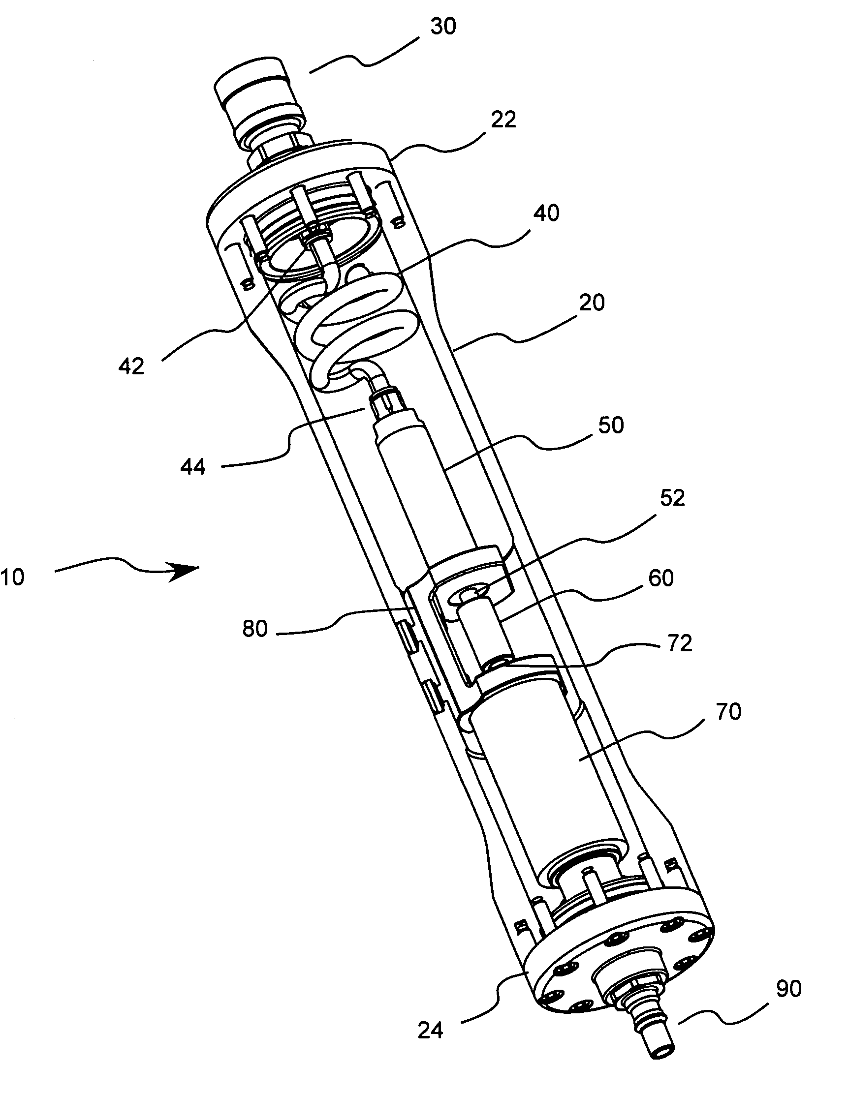
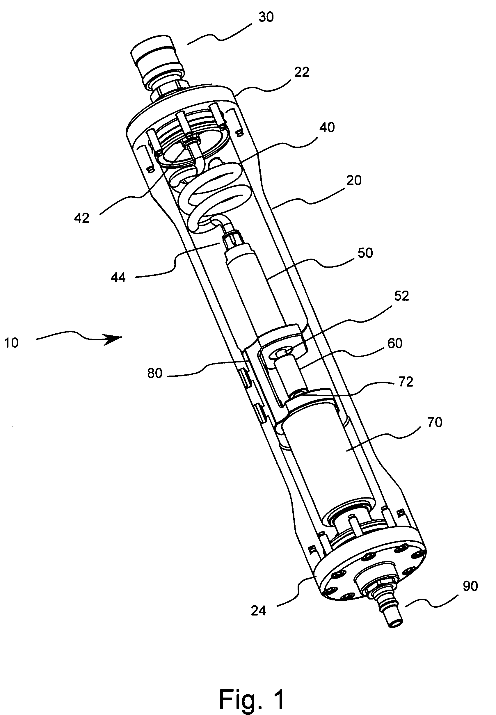
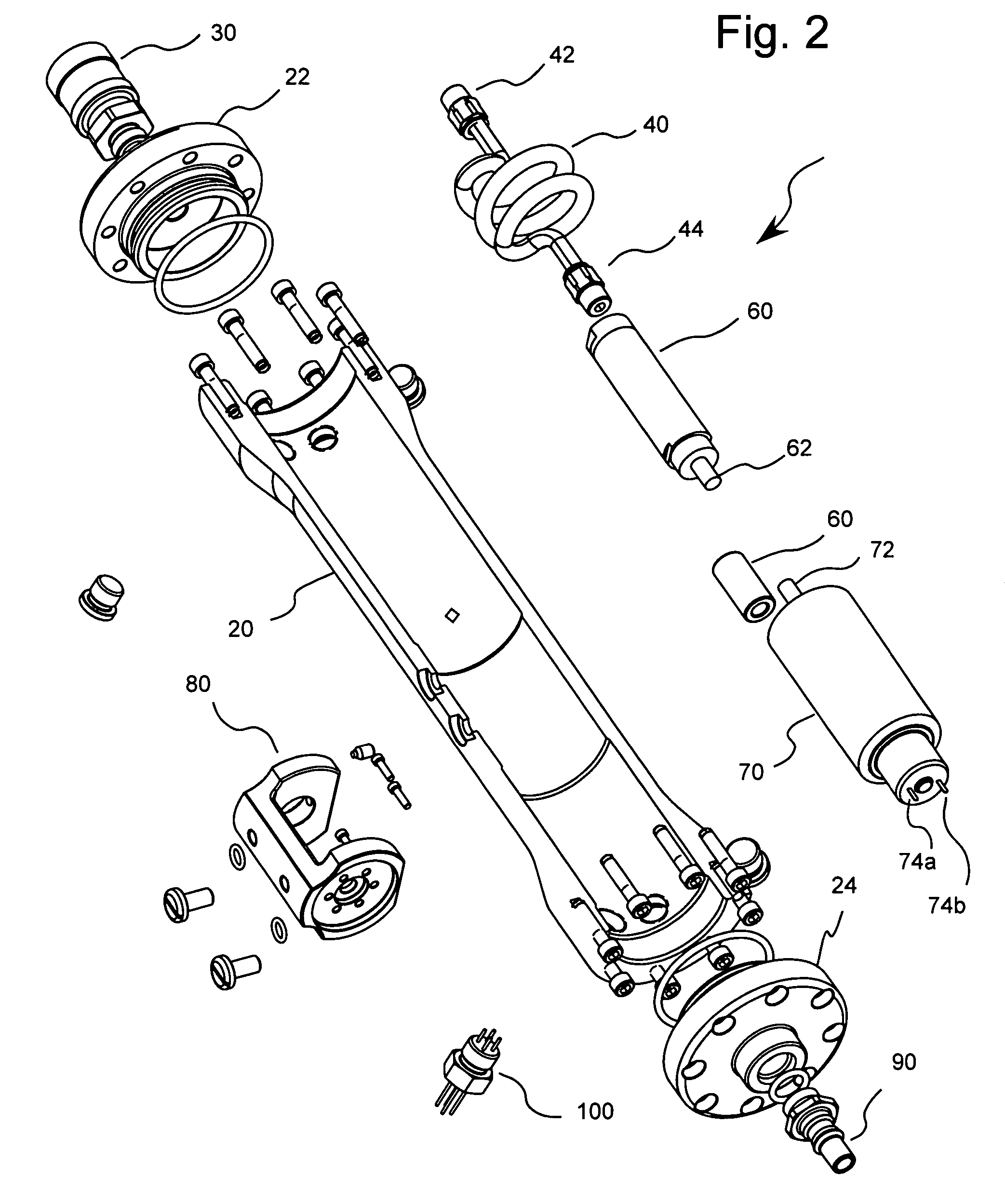
[0028]FIGS. 1 through 4 illustrate an embodiment of a generator system 10 of the present invention which includes a housing having a generally cylindrical housing section 20. The housing also includes a first end section 32 and a second end section 24. An inlet port 30 is provided through which pressurized gas (for example, compressed air from a cylinder 210 illustrated in FIG. 4) enters housing 20. Inlet port 30 is in fluid connection with tubing 40 via a connector 42. Tubing 40 is also in fluid connection with an air turbine or air motor 50 via a connector 44. An example of a turbine suitable for use in the present invention is Model MMF 0700 available from Micro Motors, Inc. of Santa Ana, Calif. Air turbine 40 includes a shaft 52 which is caused to rotate by the pressurized gas flowing through air turbine 50. The pressurized or compressed gas which causes rotation of shaft 52 exits turbine 50 into housing 20, which is preferably sealed (other than inlet port 30 and an outlet port...


PUM


Abstract

A breathing system includes a container to store a gas under pressure, wherein the gas includes air or oxygen. The container includes an outlet through which the gas exits the container. The breathing system further includes a generator system including a generator in operative connection with the container outlet such that energy is supplied to the generator by the pressurized gas. The generator converts the energy supplied by the pressurized gas to electrical energy. The system further includes a fluid path in connection with the generator through which pressurized gas passes after providing energy to the generator and a respiration facepiece in fluid connection with the fluid path.

Description

FIELD OF THE INVENTION[0001]The present invention relates generally to devices, systems and methods for generating electricity from gas stored in a container under pressure, and especially, to devices systems and methods for generating electricity from pressurized air delivered to a self-contained breathing apparatus.BACKGROUND OF THE INVENTION[0002]A generator and a motor are essentially the same device mechanically. The term applied to a particular device depends on whether (i) electricity is input into the device to cause rotation of an armature (a motor) or (ii) energy is produced by the device by spinning an armature by an input torque (a generator). Generators (both DC and AC) use magnets to transform mechanical energy into electrical energy via magnetic induction. Generators have a main magnetic field, which can be produced by a permanent magnet or by a coil called a field winding located in the stator or the rotor. Conductors make up the armature winding (coil) which is usua...

Claims


Application Information

Patent Timeline
Patent Type & Authority Patents(United States)
IPC IPC(8): F03B13/00A62B7/00A62B9/00F02C1/02F02C3/30
CPCA62B9/00F02C1/02Y02T50/671Y02T50/60
Inventor HENDRICKSON, JAMES A.MARANGONI, ROY D.PALAMARA, MATTHEW J.
Owner MINE SAFETY APPLIANCES CO
Why Eureka
Try Eureka